
Most of the time, a new created plane is designed relatively to the current workplane defined in the control bar. We advise you to check that this one is correct before designing your workplane. When you design a workplane, it automatically becomes the current workplane and it is displayed in the active window. A non-modifiable order number is automatically assigned.
Commands for Workplanes Creation
The planes creation commands are available in the Workplanes menu:
|
Icon |
Name |
Explanation |
|
|
|
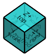
Homogenized command allowing for versatile modes of workplanes creation. The users can choose with which methodology they are more at ease with and also can be adapted to various situations. On launching the command, a blue cube appears on the bottom right of the screen and the user can directly click any face on the cube to generate a plane in that orientation quickly. The interactive axis system, in the bottom right corner of the screen also starts the command by clicking and dragging its origin to a point or a face required. |
|
|
|
|
Creation of a plane especially dedicated to the machining cycle called Profile cutting. |
||
|
|
Creation of a plane developed around an axis. |
||
|
|
Projection of the geometry in a developed plane. |
||
Other Specific Commands
|
Icon |
Name |
Location |
Explanation |

|
Edit/Change Plane |
This command helps to change the workplane of wireframe or solid elements. |
|
|
|
Part Positioning |
Design/Wireframe/Cleaning Design/Solid/Repairing |
Positioning the part in the reference plane; click on 3 points on the part: new origin, X direction, Y direction. |
|
|
Wireframe/Cleaning |
Position in 3D space of the views and the details of a 2D draft. |
|
|
|
Axial Plane |
In Turning Environment Design/Part Design/Axial Plane |
Creation of an axial plane. |
Comparison with Previous Commands
The following table is being made available for long term users and users of the previous versions of GO2cam to facilitate their transition to the new version. All the previous available commands are still possible to be reproduced but with a more homogenized process.
|
Previous Version |
As from V6.12 |
|||
|
Icon |
Name |
Description |
|
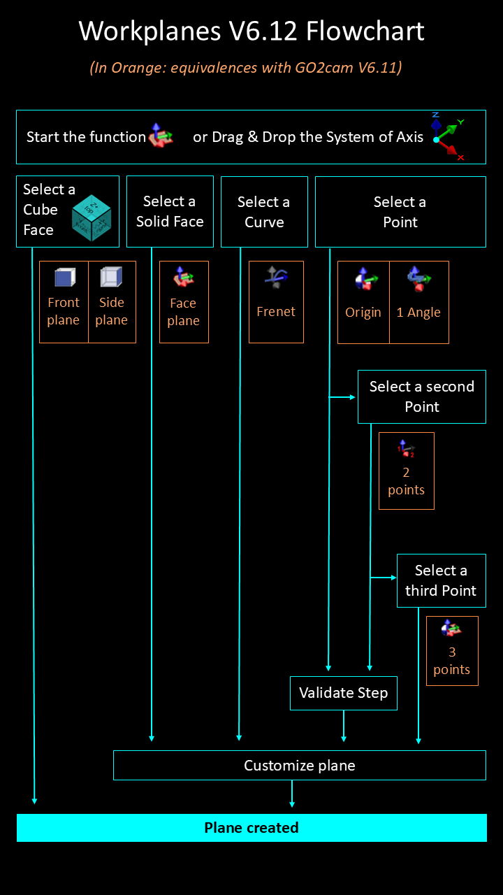
All the listed commands have been merged into a single command. View the flowchart below showing the new processes and how they produce the results of the previous commands. |
|
|
3 Pts X or Face Plane |
Creation of a plane by 3 points which are defined in the order of selection: the origin, the X direction, and the Y direction. On a solid, you can click a face directly. By clicking a cylinder, you create the plane corresponding to the Z direction of the shape. |
|
|
|
|
2 Pts X Plane or Section |
Creation by 2 pts which define in the order of selection: the origin, the X direction. It is perpendicular to the current plane. |
||
|
|
1 Angle Plane |
Creation of a plane by rotation around the X, Y or Z axis relative to a reference plane (the current plane). |
||
|
|
Origin Plane |
Creation of a plane parallel to the current plane with another origin. |
||
|
|
3 Pts or Face Plane |
Creation of a plane clicking on 3 points, then you can permute the axis and finally you choose the plane origin. |
||
|
|
Front Plane |
Automatic creation of the Front plane, relative to the current plane. The origin is the same as the current plane. |
||
|
|
Side Plane |
Automatic creation of the Side plane, relative to the current plane. The origin is the same as the current plane. |
||
|
|
Manual Plane |
Creation of a plane by the manual selection of position |
||
|
|
Plane of Frenet |
Creation of a plane perpendicular to an element extremity with the z axis tangent to the element. |
||
|
|
3 Angles Plane |
Creation of a plane by combination of angles: CAC (ZXZ), CBA (ZYX), CBC (ZYZ) or CAB (ZXY). |
||