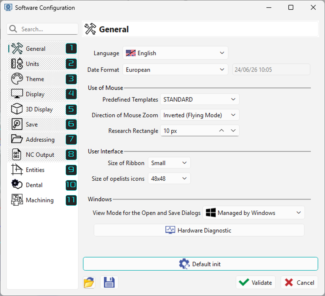
The user interface can be customized to the customer's preferences. The Tools / Options menu offers many options organized into several categories:
|
|
|
User interface preferences, including language, formats, mouse behavior, menus, and window settings. |
|
|
Geometry units, machining units, measurements, and others. |
|
|
|
Please read the chapter below about themes, |
|
|
|
General, axis systems, screen texts, visual behavior. |
|
|
|
Light source, advanced graphic options. |
|
|
|
Automatic saving, backup files, and more. |
|
|
|
General, production, machining, environment. |
|
|
|
Settings for Post-processor and treatment of NC codes. |
|
|
|
Automatically update after modification and trace symbol precision. |
|
|
|
Customize the programming process and activate output for some association files |
|
|
|
Customize the usage of 'Produce' functions |
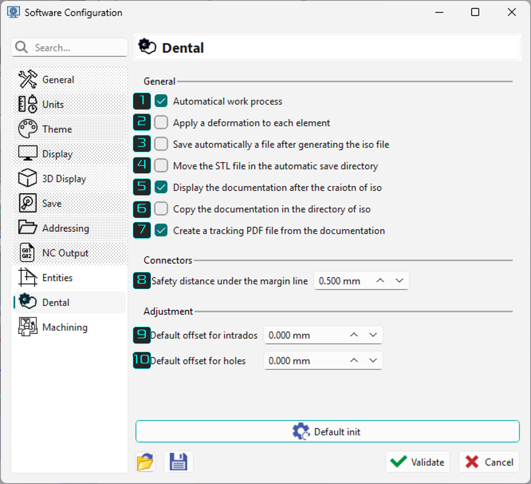
Details of ‘Dental’ and ‘Machining’ in Software Configuration
Dental
|
|
|
|
Enables to chain automatically all the actions necessary for the production of a tooth |
|
|
Enable to apply a rescale coefficient different for each tooth |
|
|
Enables to save automatically a file of the current project |
|
|
Enable to move automatically the original STL file to the automatic saving directory once the machining is complete |
|
|
Once the post-processor is launched, displays a document of the whole project |
|
|
Copies the document in RTF format besides the NC file generated in the iso directory |
|
|
Enables to create a PDF file of the document to ensure a traceability of the job done |
|
|
Defines the distance between the created connector and margin line |
|
|
Default offset values considered in the program window. |
|
|
|
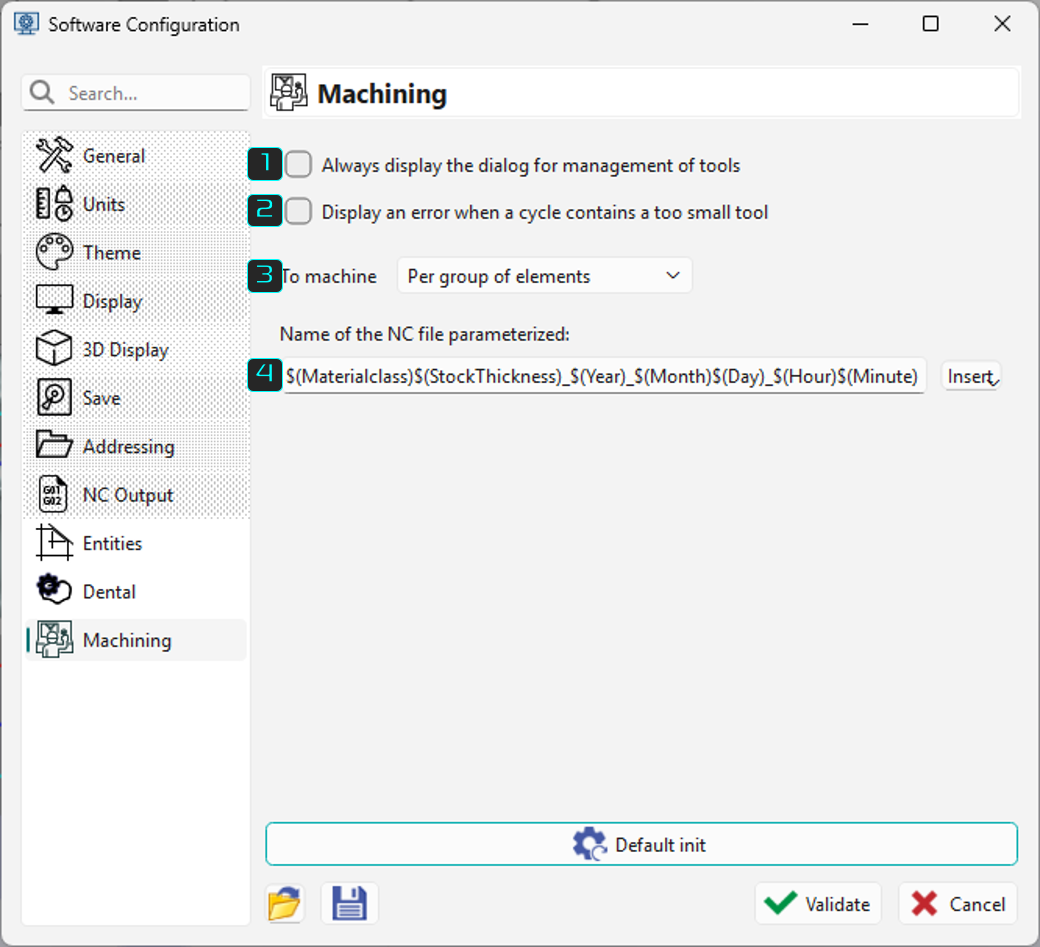
Machining
|
|||
|
|
Shows the window to define tool positions each time users generate an NC file. |
||
|
|
Displays an error message if the tool is too small. |
||
|
|
Define a method to optimize machining multiple elements. Per group of element: Apply the first cycle to all elements, then the second cycle to all elements, and so on. Element by element: Apply all cycles to the first element, then to the second, and so on |
||
|
|
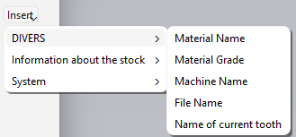
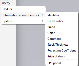
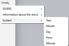
Reset the NC file name. If left empty, the default name applies. Users can click the Insert button to add more details to the NC file name or type words like their name to include in the output. |
||
|
|
|
|
You can customize behaviors such as displaying opelists in a menu, mouse navigation, and selecting a specific text editor.
Some options fix display problems.
You don't need to repeat the steps each time you start GO2cam; it remembers your latest configuration.
In English installation, tools and strategies use millimeters by default. To switch to inches, go to the workshop and select Software Configuration.
-
To work in inches with Imperial display, click the Units option, then select Imperial from the Unit System drop-down list.
-
Software configurations save in .ini files and can be loaded by clicking the drop-down list.
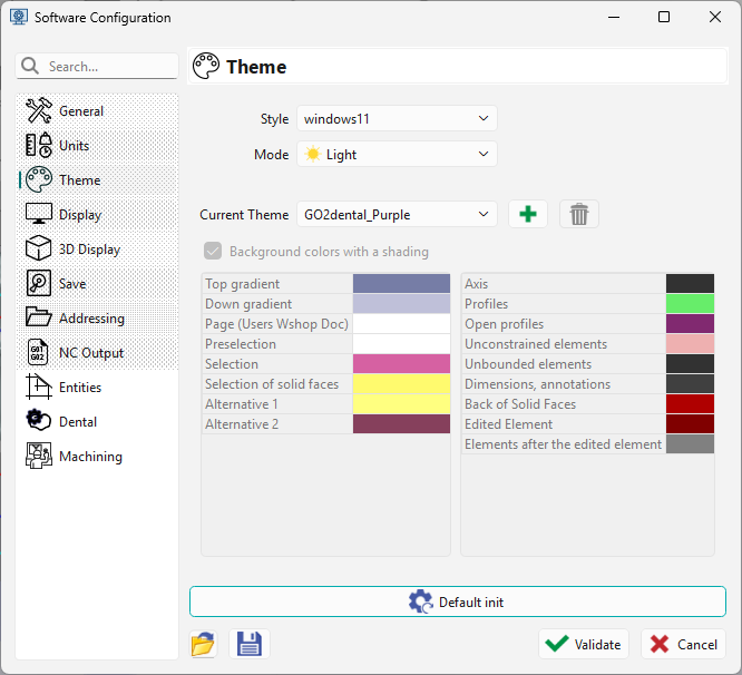
Themes of the user interface
A theme includes:
-
Background colors, with optional shading,
-
Menu and toolbar colors,
-
Colors of highlighted and selected commands,
-
Menu text colors,
-
Colors of miscellaneous elements like profiles, unbounded elements, and selection.
Themes also include display options:
-
Tree display with transparency,
-
Tree display on the left or right of the screen,
-
Size of the interactive axis system.
A theme can be saved with user choices by clicking the icon. This theme is added to the list of themes. Each software (GO2cam, GO2operator, GO2designer) has its own theme. We also offer two themes for part layouts, with white and black backgrounds. You can select the ‘Default theme’ to reset options to original values.
Two option pages configure a theme: User Interface and Interface Colors shown on the right.
Colors are chosen for each element by clicking the corresponding color icon.
Be careful choosing some colors: for example, white axes won't be visible on light backgrounds!