
|
|
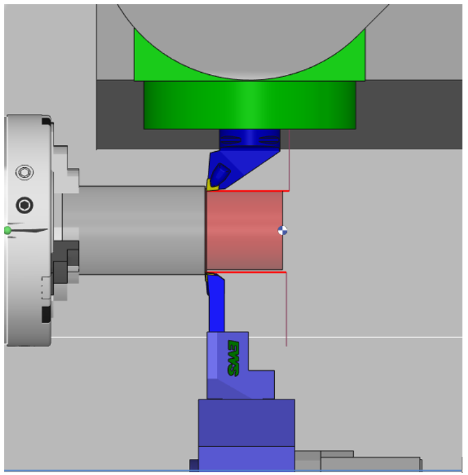
Roughing operation programmed with 2 tools mounted on 2 turrets (or spindle) and synchronized by different possible modes. The toolpaths can be outside, inside or facing. |
This machining cycle is available only with the optional module MTE.
The standard simulations (Dynamic and Toolpath) will not show the reality of the cutting, the synchronizations and a possible different second tool. You should always simulate balanced operations with MTE control simulation.
Key Points
|
For turning machines with dual turrets, mill-turn machines as well as Swiss machines, balanced operations unlocks new possibilities by allowing users to program simultaneous turning operations using tools on the opposite sides.
|
|
|
You can watch a video explaining the application of balanced synchronized cycles. At 2.20 in the video, view the definition of two different tools for the cycle. This applies when using a single tool loaded twice, enabled by the function 'Add a different opposite tool', accessible via right-click on the tool in the machining tree. In MTE, if you do Auto mount, these 2 tools will automatically be mounted on opposite turrets. More details can be found in the following FAQ by clicking the link here. |

|
Strategy Parameters
|
Dialog Area |
Parameters |
|
|
Toolpath |
||
|
R max Coef |
||
|
Synchronization |
||
|
Machining Strategy |
||
|
Retract |
||
|
Angle of passes |
||
|
XY Stock allowance |
||
|
Deburring |
Z Stock allowance |
|
|
|
||
|
Chip breaking |
||
|
|
||
Movement Parameters
|
Dialog Area |
Parameters |
|
|
Approach and Return Characteristics |
||
|
Over cutting |
Undercut safety distance |
|
|
|
||
|
Facing |
Linitate on Z axis |
Exceed the the axis |
Technology Parameters
|
Dialog Area |
Parameters |
|
|
Cutting Conditions |
Quality |
Cutting Speed |
|
Spindle speed |
Speed range |
|
|
Feedrate in Z |
Feedrate |
|
|
Feedrate in X |
Spindle direction |
|
|
Pass feedrate |
Maxi spindle speed |
|
|
Tool number |
Specific Number |
|
|
Radius compensation number |
Length compens. nb |
|
|
|
||
|
Opposed Tool Numbering |
Tool number |
Specific Number |
|
Radius compensation number |
Length compens. nb |
|
|
|
||
|
Users Fields |
Comment |
Control Device |
|
Machining Set |
|
|
Options Parameters
|
Dialog Area |
Parameters |
|
|
Management of collisions |
||
|
Curves Computing |
Curve Tolerance |
Curve explode into |
|
Options |
||
|
Compensation achievement factor |
Coeff of feedrate reduction |
|
|
|
||