
Revisions are GO2cam versions mainly dedicated to fix software issues. Revisions are identified by numbers 201, 202, etc. and they are released approximatively once a month.
Minor improvements are sometimes added, they are described in this document. For the whole list of corrections, click here.
V6.12.208
|
Improvements |
07 October 2025 |
|
Topic |
Type |
Subject |
Explanation |
|
|
|
Turning Geometry |
|
Local Stock Allowance |
We improved the local stock allowance display: text size, position and highlight of currently selected segment. |
|
|
Milling Features |
|
Settings |
Features Recognition: in the Settings dialog, we added a new checkbox that enables to choose or not to apply standard models to holes. If checked and if no user model match with the recognized hole, then we do not apply standard model and the holes is not machined. |
|
|
Machining Generalities |
|
Profiles |
A machining profile based on hidden geometry was not visible while editing the operation! We changed this behaviour and the profile is now visible while editing machining, even if corresponding geometry is hidden. |
V6.12.206
|
Improvements |
29 July 2025 |
|
Topic |
Type |
Subject |
Explanation |
||
|
|
Wireframe Design |
|
Reading Points File |
While reading a file of points file in Turning, you can now choose whether coordinates are expressed in XYZ or ZXY, so that the points can be created in the Revolution plane. |
|
|
|
Post-Processors |
|
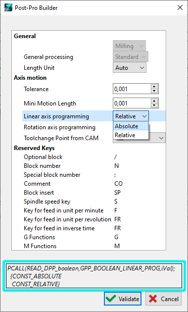
PP builder |
In the table of parameters, we added a field at the bottom of dialog to visualize the ID of Pascal function for each parameter. |
|
V6.12.205
|
Improvements |
08 July 2025 |
|
Topic |
Type |
Subject |
Explanation |
|
|
|
Milling |
|
2 new parameters 'Linear Overlengths' in contouring. They are applied at the start and at the end of profile. They can be combined with Start and End Overlengths, which extend or shorten the element in tangency. |
|
|
|
Post-Processors |
|
PP builder |
New button in PP Builder to open G-codes file directly. |
V6.12.204
|
Improvements |
10 June 2025 |
|
Topic |
Type |
Subject |
Explanation |
||
|
|
GO2cam for SolidWorks |
|
User Interface |
In SolidWorks customization, it is possible to modify icon size. It is now supported by the plugin. |
|
|
|
Mesh Design |
|
Nesting |
Nesting mesh models is now possible (STL format files) |
|
|
|
Workplanes |
|
|
Improvement in the New automatic method for Machining in Developed Plane, (implemented in 6.12.202). Now, when you are creating profiles and no diameter has been entered yet, with a single click on the reference cylinder, the profiles are created and the diameter entered. |

|
|
|
Wire EDM Geometry |
|
Table of Threading Points |
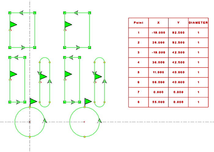
New Macro JavaScript that creates a table with Threading Points coordinates.
|
|
|
|
|
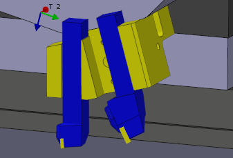
Management of holders with multiple tools. |
Some Multi-tasks machines can mount holders with multiple tools, and offer for instance 12 stations for 24 indexing positions! For GO2cam, each holder was only one tool! One indexing position and one number! From Version 6.12.204 we can manage this situation! |
||
|
|
||||
|
|
MTE |
|
Machining Tree |
The techno function Machine command is now accessible in the Machining Tree, under the line Machining. Useful in Robot and Swiss Machining Projects. |
|
V6.12.203
|
Improvements |
29 April 2025 |
|
Topic |
Type |
Subject |
Explanation |
||
|
|
Wire EDM Geometry |
|
New Option in Part Analysis: Export Threading Points Export Threading Points enables to generate the list of threading points with their coordinates and diameter value. The file format is *.xml. Note: the part analysis also works on 2D Profiles! |

|
|
|
|
Wireframe Design |
|
Menu |
The menu ‘Specific EDM’ is now available in other modules. It is called ‘Mechanical Design’ and includes the following commands:
|
|
|
|
Wireframe & Solid Design |
|
Chamfer Creation |
New option Invert Chamfer When you draw a chamfer with 2 values distance/distance, you can now invert values on the 2 selected elements or solid corner. Also possible for distance/angle mode in wireframe only. For solids, read below! |

|
|
|
Solid Design |
|
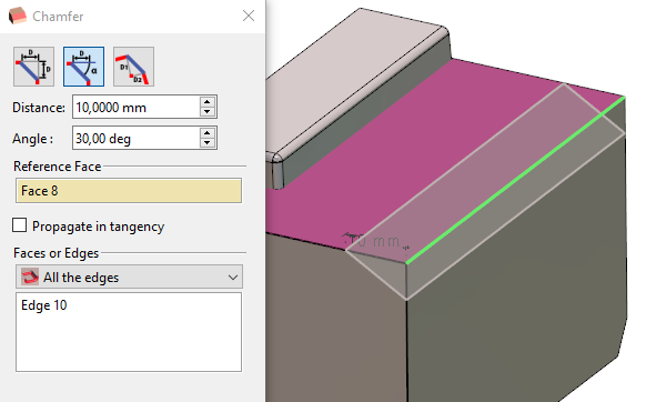
Chamfer Creation |
Solid chamfer: in distance/angle mode, new ability to select a Reference face. 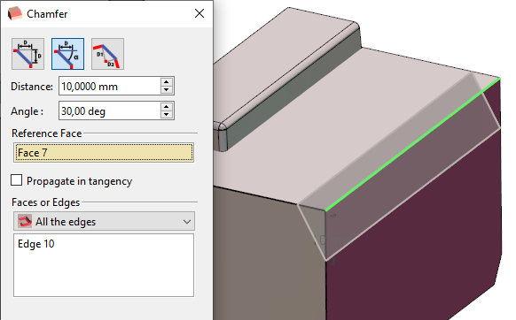
|
|
|
|
Solid Design |
|
Stop Faces |
Multiple Selection in Stop Faces With the edges path mode, multiple selection is now possible. |
|
|
|
Solid Design |
|
Simplification |
Simplification in Popup menu now opens a dialogue where you can set the tolerance value. Right-click on a solid>Utilities>Simplification |
|
|
|
|
Interfaces Versions |
CAD Formats updates:
|
||
|
|
|
Solid Import |
If a CAD file is imported as surfaces, we apply a treatment to transform the model automatically into solid. If the attempts fails, an error message is displayed. |
||
|
|
|
Mesh Import |
Explode Mesh We now have the ability to explode a mesh when it is composed of several separate components. This works the same way as with solids. If a mesh is separate, do a right-click and there you can find the "Explode" function, allowing you to decompose it into individual meshes. |
||
|
|
Machining Generalities |
|
Machine Pack |
Improvement in the new feature: Export Machine Pack The pack export is created in thread to be able to continue working in GO2cam.
|
|
|
|
Machining Generalities |
|
Machine File |
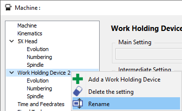
New ability to rename the ‘Work Holding Device’ in the tree. You can call it as you wish according to your machine kinematics. |
|
|
|
Machining Generalities |
|
Probing |
Probing operations are now supported on mesh parts and stock. |
|
|
|
Machining Generalities |
|
Customize List of Operations |
2 new parameters are available in the ‘Customize List of Operations’
|
|
|
|
Swiss Machining |
|
Program operations on X minus Depending on the tool orientation and the part size, axial milling on the C axis is only possible if the part is properly positioned relative to the tool.
|

|
|
|
|
Milling Features |
|
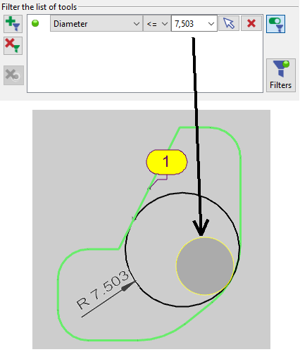
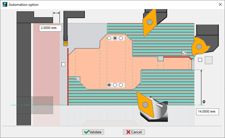
Inscribed Circle |
New parameter of Inscribed Circle.
For instance, the pocketting of a circle or cylinder will now define a filter of half the diameter! On the right, we see that the inscribed circle is diameter 15.06, so radius 7.503. The tool filter is set to 70.503 mm. |
|
|
|
Milling |
||||
|
|
MTE |
|
Synchronizations |
2 great improvements in the setting of synchronizations:
|
|
|
|
MTE |
|
Machine Creation Module |
2 improvements in the module for Creation of 3D Machines:
This module is only available for Resellers. |
|
V6.12.202
|
Improvements |
26 March 2025 |
|
Topic |
Type |
Subject |
Explanation |
||
|---|---|---|---|---|---|
|
|
Workplanes |
|
|
New automatic method for Machining in Developed Plane. This new command is a wizard where you should:
Once done, the developed plane is automatically created, with the geometry projected in the plane and the toolpath! This command is available in Turning configuration, in the Standard and Manual menus, then Selection of Geometry. |
|
|
|
Tooling |
|
Broaching Tool |
New process for the creation of a broaching tool: creation of 2 elements (insert and body) in the Clamping/Toolholders environment. The tool file is now created directly in the tools' library of the menu Broaching and disappeared from the environement ‘Tools Libraries/Forming Tools’ |
|
|
|
Turning |
|
Broaching |
New ability to program broaching operation offcenter. Previously, the tool had to be aligned with Z axis. Now, with the new computing method, you can program broaching offcenter. |

|
|
|
|
Automatic Turning Opelists |
New options to enable the complete machining of part on the Main Spindle For external and internal machining, we have now 3 modes of machining:
|
||
|
|
Machining Generalities |
|
Table of Origins |
If an operation is programmed on a plane and has a special origin defined in the table of origins, and if a new operation is programmed on the same plane, we apply the same origin to this new cycle. |
|
|
|
Opelists / Strategies |
|
Opelists |
We added 3 new functions to recover a measure according to X, Y or Z and assign it to a parameter in the Opelist |
|
|
|
|
Developed toolpath |
When launching the step-by-step mode, the speed was automatically set to default value; now, if the cursor value is below the default, we keep it slow when running step-by-step. This new behaviour enables to simulate toolpath on developed plane such as wrapped groove on a turnmill lathe. Previsously, the simulation was always too fast! |
|
|
|
|
|
Display system of Axis |
The system of axis displayed in the simulation is modified according to the machining plane of each cycles simulated. |
||