
Manual connector – Disk
|
Click at the icon to create the connector manually. |

|
|
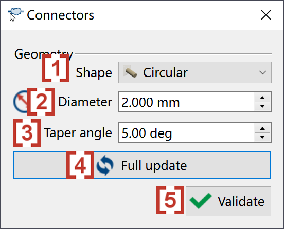
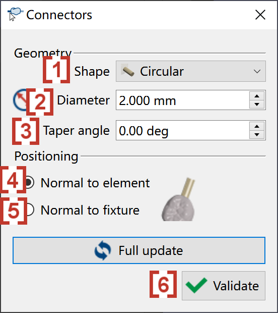
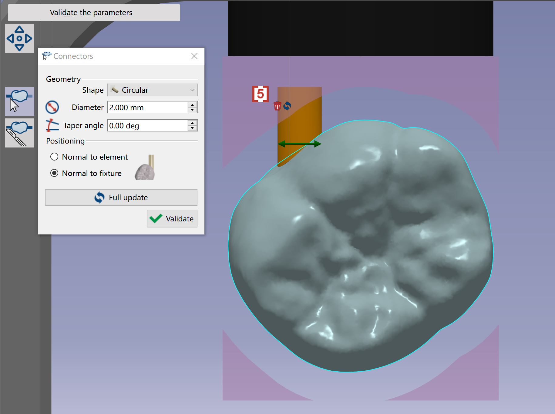
In the pop up window, we can define the Shape [1] , Diameter [2] and Taper angle [3] of the manual connectors to be created. We can click at 'Full update' [4], and then all the connectors of this element will be updated with the current definition. When all connectors are corrected created, we can click at validate [5]. |
|
|
You have 2 ways to create a manual connector:
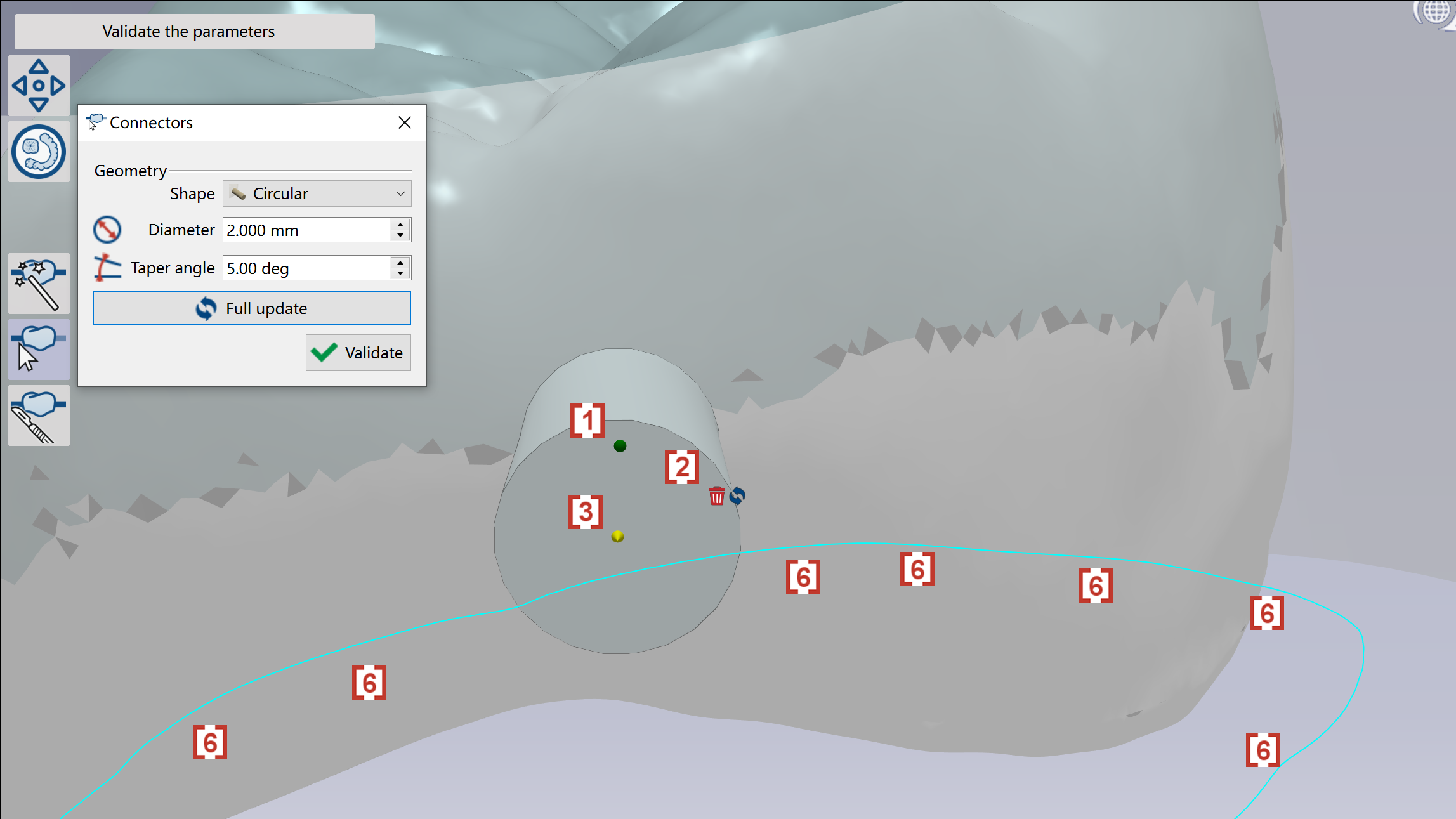
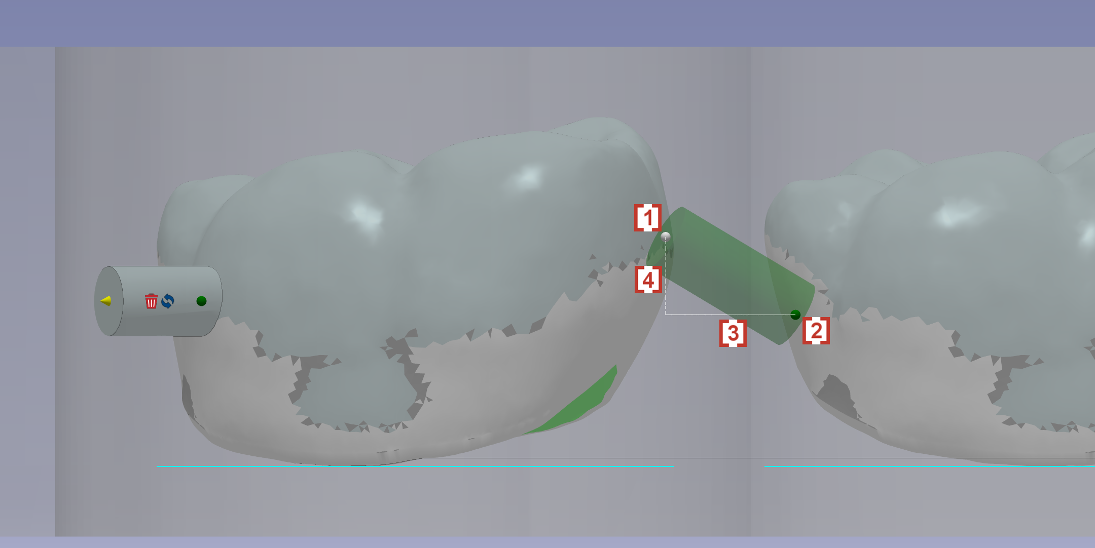
A green ball [1] will also be created at the location where connector is created. We can drag the green ball to change the location of the connector. We can click at the trash icon [2] to delete the connector. We can also drag the yellow arrow [3] to extend the connector to be connected with another element [4]. The connector will finally become a connector between 2 elements [5]. |
|
|
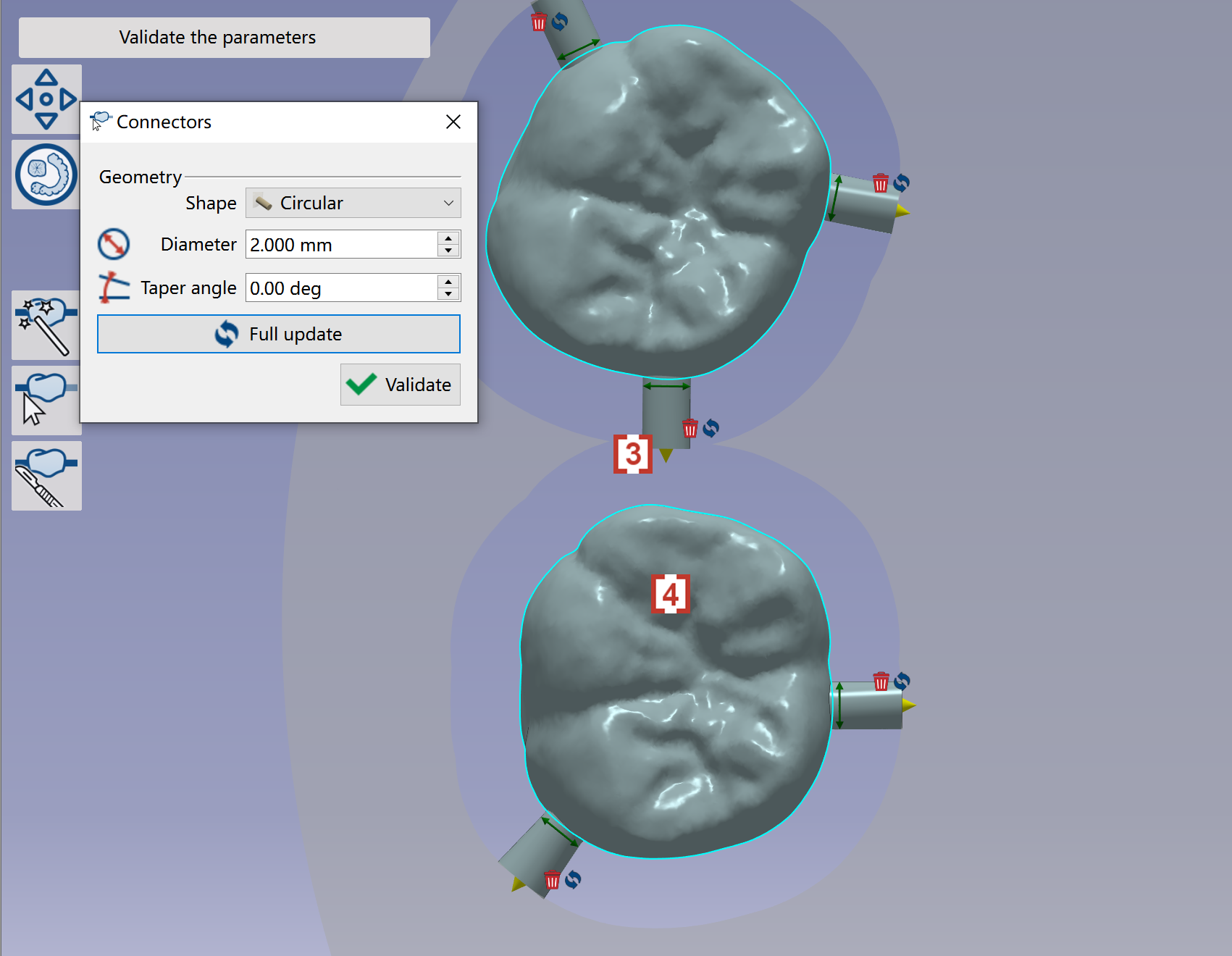
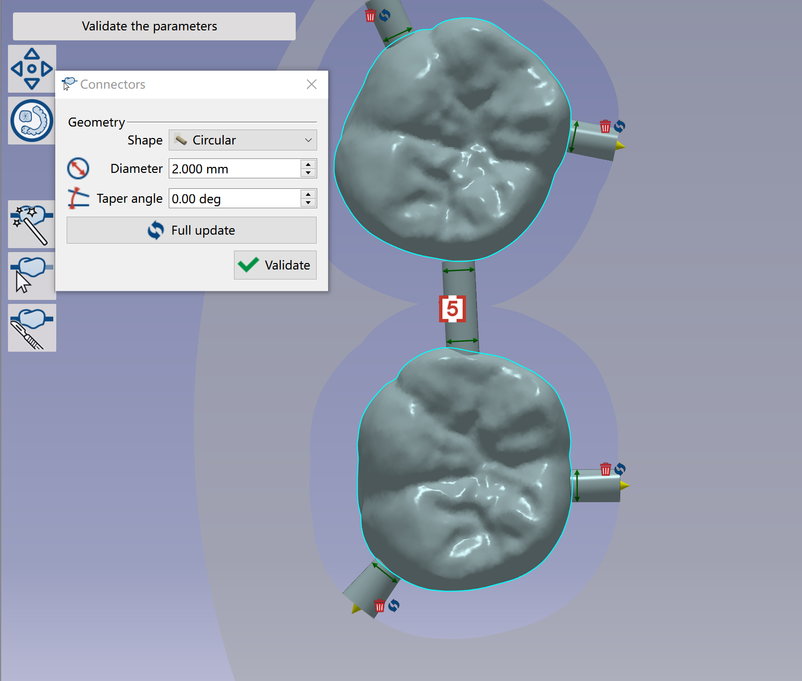
For the connectors between 2 elements, we can drag the 2 ends of the connector to modify the locations. During the move of the 1st end [1], a horizontal line cross [3] the 2nd [2] end will be displayed to help you control the Z difference [4] of 2 ends. |
|
|
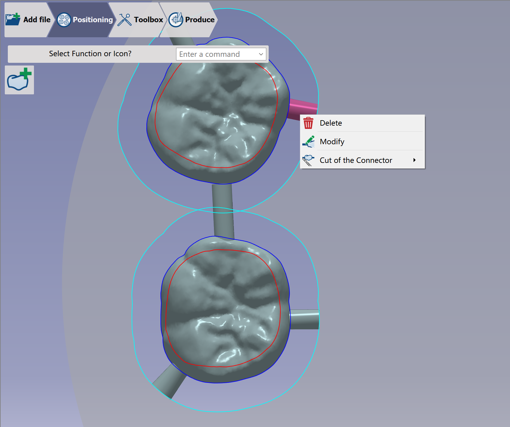
If you want to delete or modify any connectors been created, you can use right mouse click at the connector and choose the action. |
|
Manual connector – Blocks
|
Click at the icon to create the connector manually. |
|
|
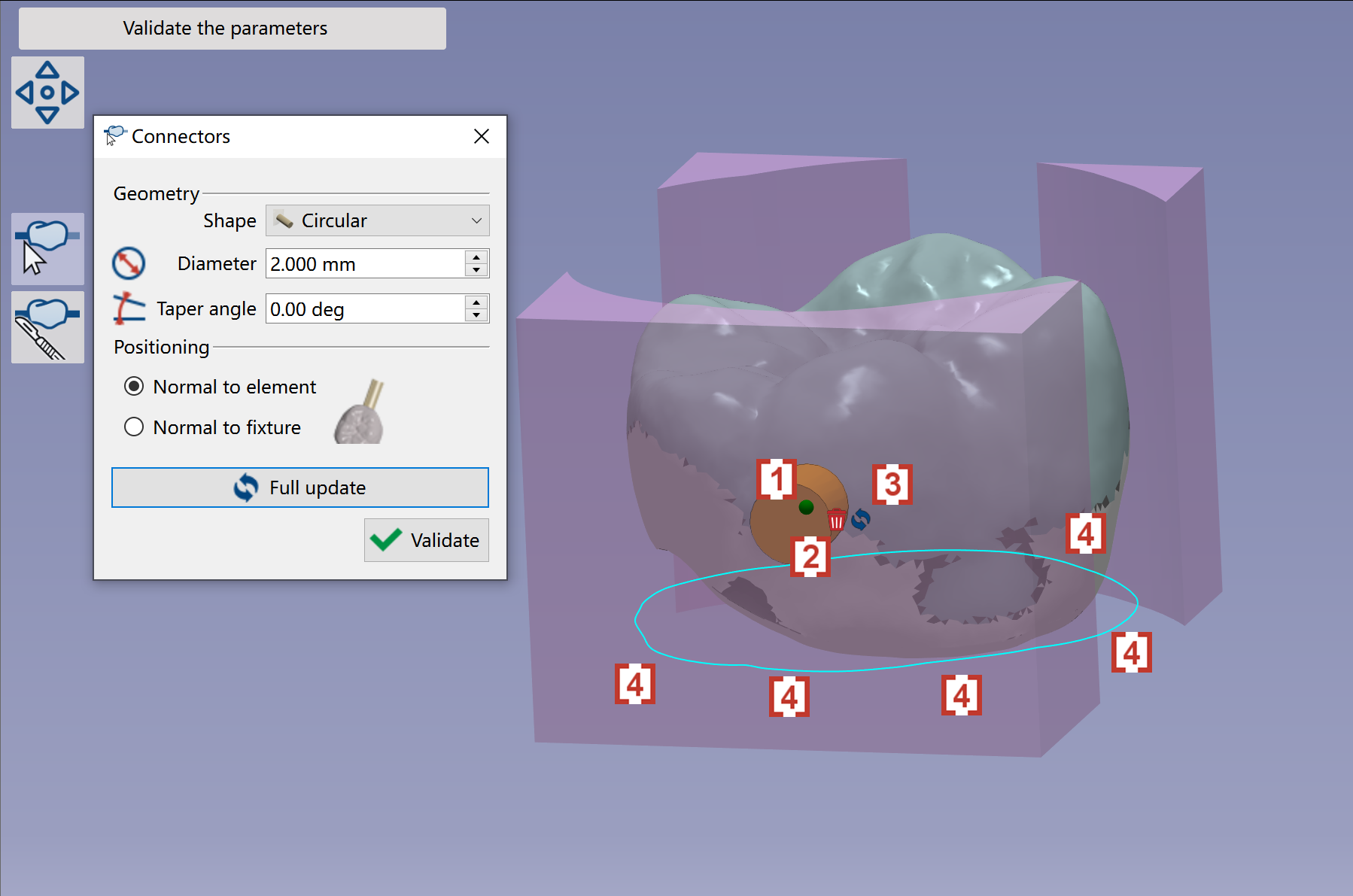
In the pop up window, we can define the Shape [1] , Diameter [2] and Taper angle [3] of the manual connectors to be created. We can choose the positioning of manual connector to be ‘Normal to element' [4] or 'Normal to fixture’ [5]. After the manual connector is corrected created, click at Validate [6] to finish the function. |
|
|
You have 2 ways to create a manual connector:
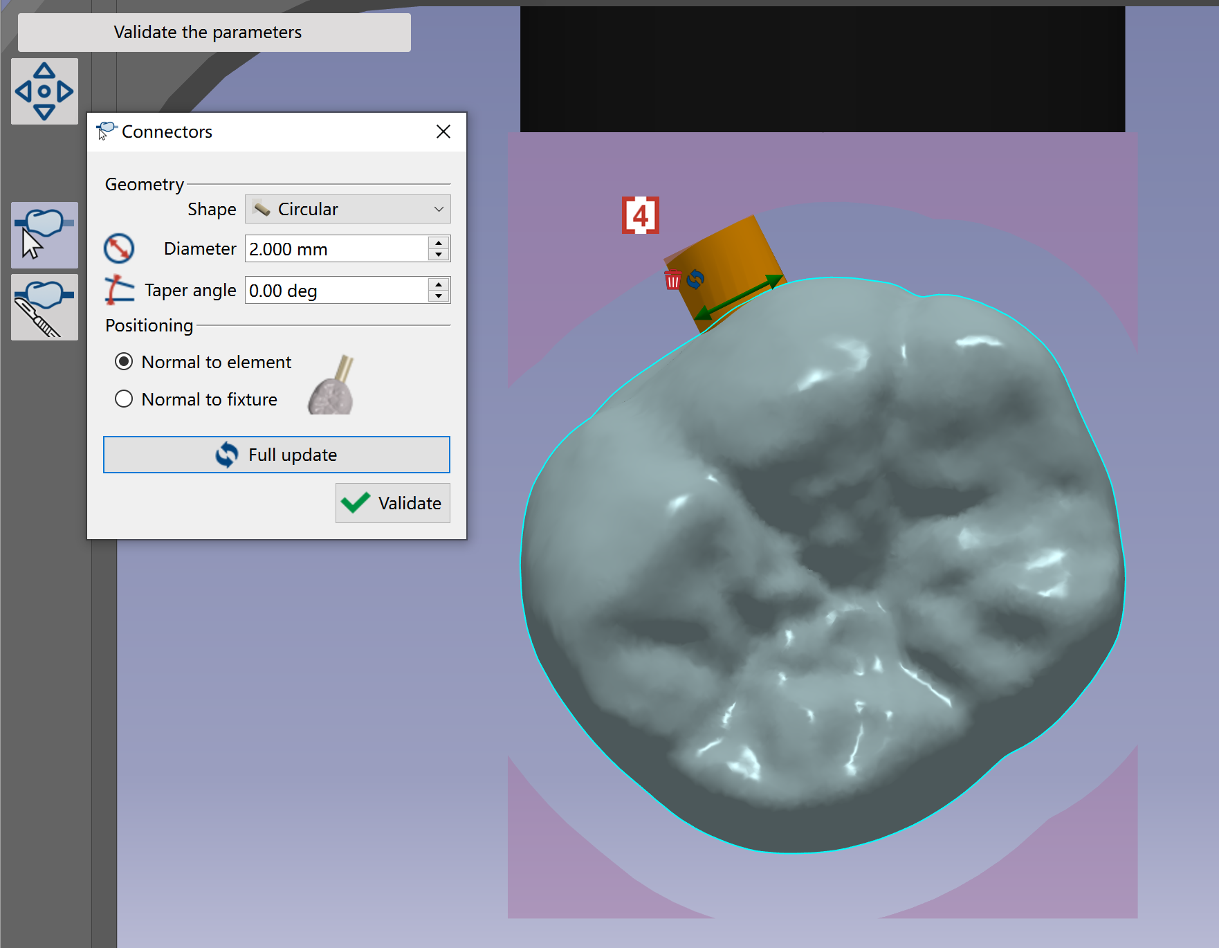
A green ball [1] will also be created at the location where connector is created. We can drag the green ball to change the location of the connector. We can click at the trash icon [2] to delete the connector. We can change the definition of connector and then click at icon of update [3], so that the connector will be updated with the new definition. |
|
|
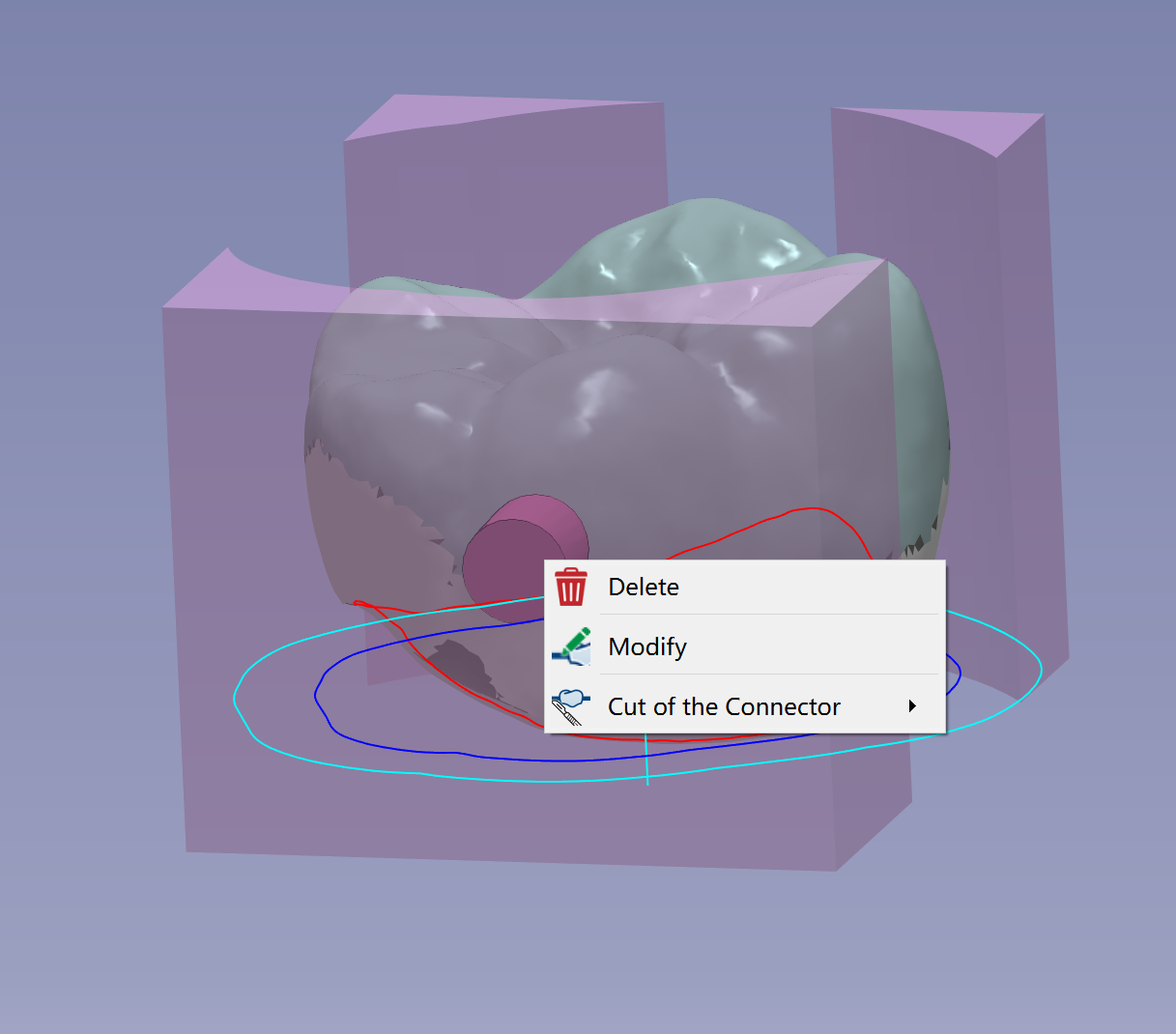
If you want to delete or modify any connectors been created, you can use right mouse click at the connector and choose the action. |
|
Manual connector - Premilled
|
Click at the icon to create the connector manually. |
|
|
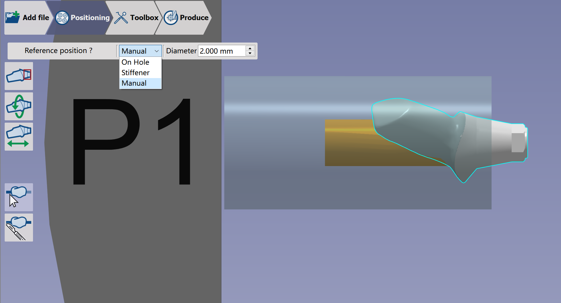
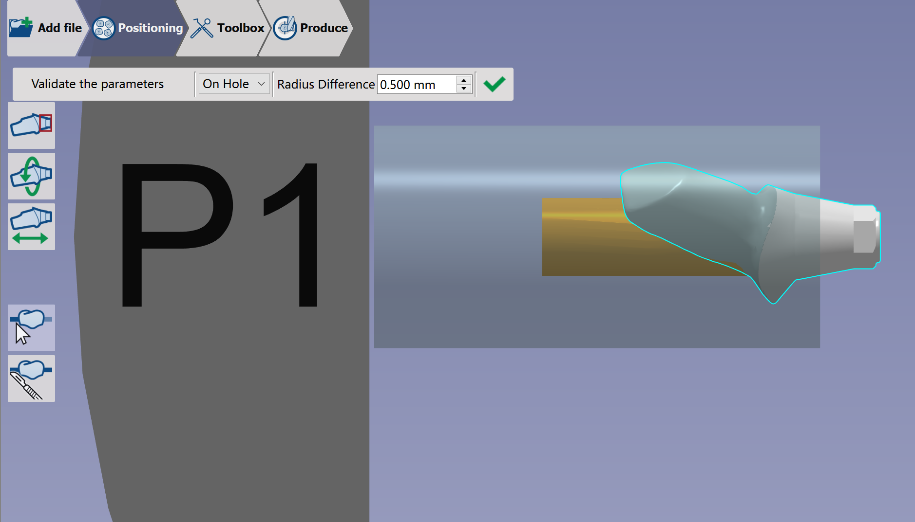
In the pop-up window, we can define the type of connector [1] and the size of connector [2] |
|
|
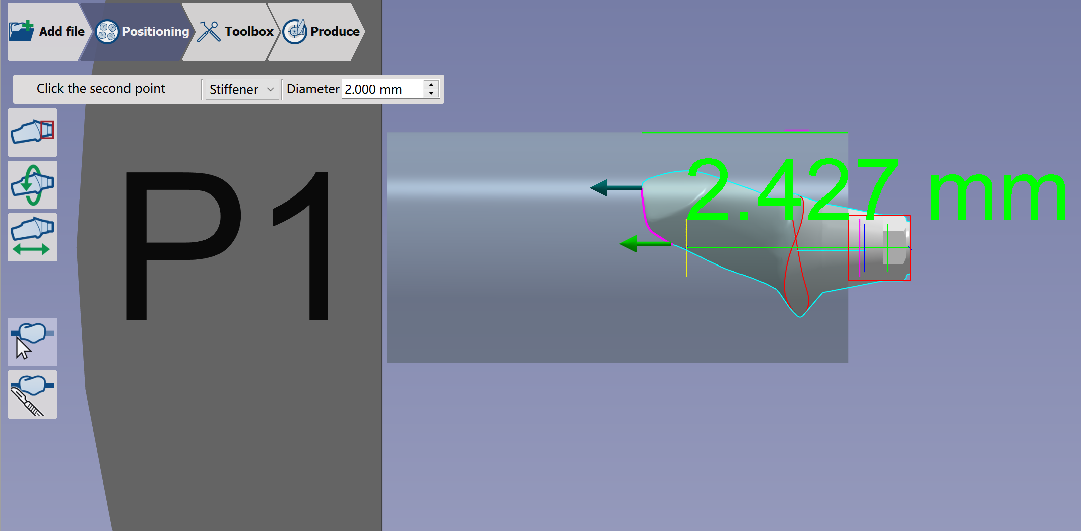
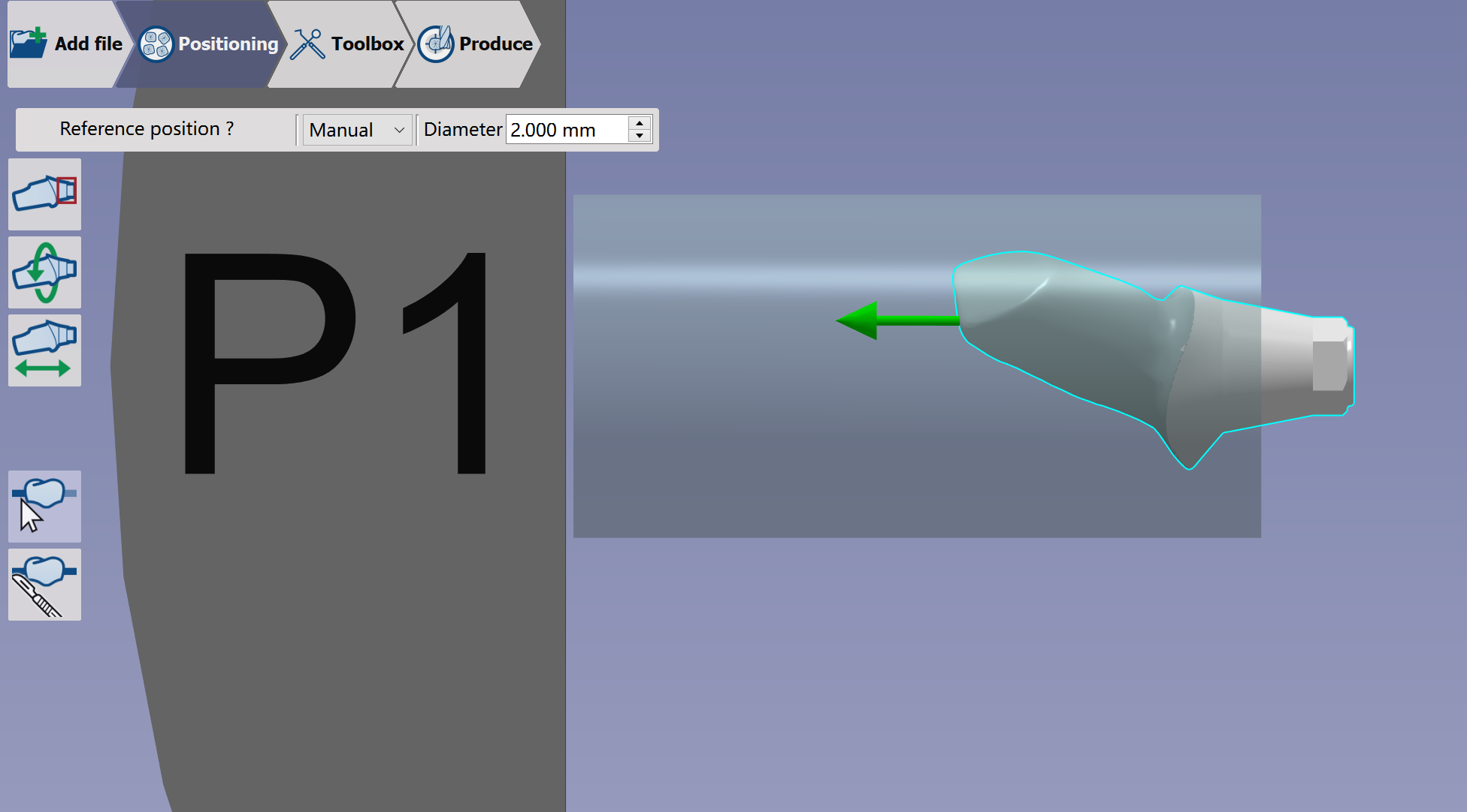
There are 3 types of manual connectors:
|
|
|
On hole: The connector is positioned automatically on the hole. This is the default type to be automatically created. Radius Difference defines the radius difference between the hole and connector. |
|
|
Stiffener: You have to indicate two points on the element to define the position of the connector. |
|
|
Manual: Possibility to position the connector anywhere on the 3D part |
|