
Change / Create Tool
1 - Create tool inside library
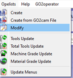
2 - Edit OPL
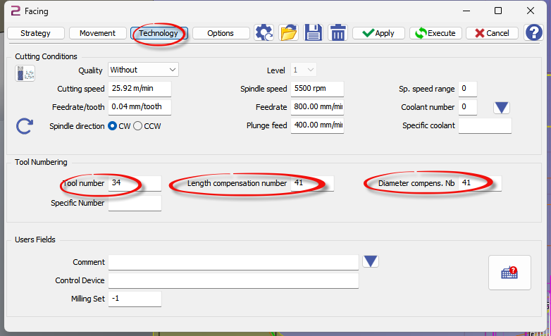
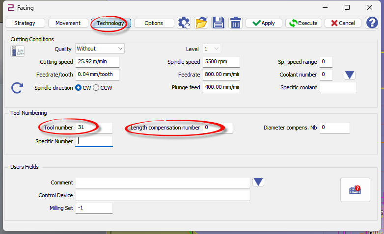
3 - Inside OPL put the correct tool numer and if needed add correct number for tool length compensation
|
T3441 M36 S5000 G17 M8 G0 C0. X20. Y0.006 T41
|
|---|
|
T3100 M36 S5000 G17 M8 G0 C0. X20. Y0.006 T31 |
|---|
Tool Path
Roughing
|
Reference (Geometry selection) 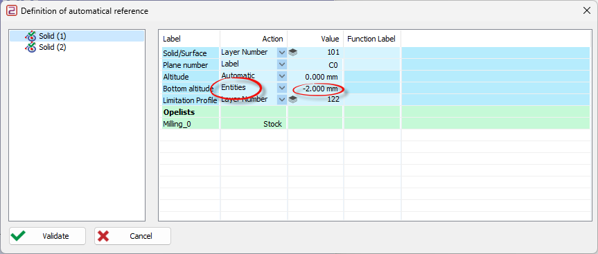
|
Bottom Altitude = ENTITY Value must be Tool radius 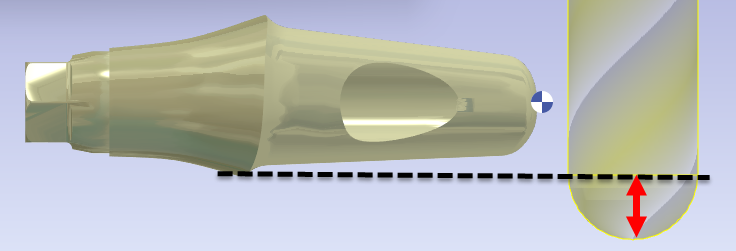
|
To save machining time is important to place abutment on position with minimum undercut - we can reduce number of pass
|
Correct placement minimum Z depth 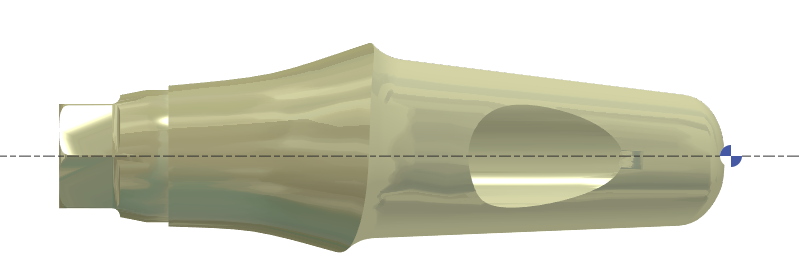
|
Not correct many pass in Z 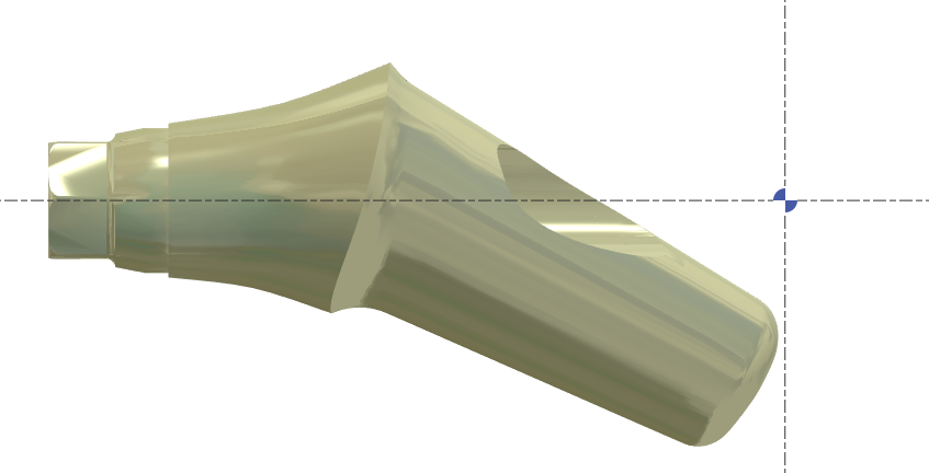
|
Setting to get the minimum air cutting
|
Stategy TAB |
Movement TAB |
Options TAB |
|---|---|---|
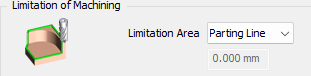
Automatique stop on the parting line. |
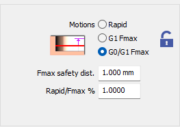
Rapid.Fmax % = 1 to have maximum of G0 for link between 2 path |
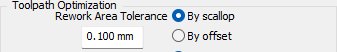
Value = 0.1 Here the stock is after turning operation so stock is very smooth no need to have small tolerance |
Force the toolpath to start from outside to inside |
|
|
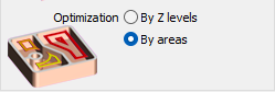
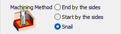
To avoid retract mouvement. Tool work area by Area |
|
|
4Xs
Automatic reference:
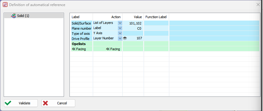
101: STL file + RED Cylinder to protect Connectic area
102: SOLID at the back to avoid to tuch occlusal face
107: Guide line used for 4Xs tool path - length can be adjust inside setting
NB: (without MTE)
|RSTATE|0|180.000000|
|RSTATE|1|270.000000|
|
Options TAB |
|
|---|---|
|
|
|
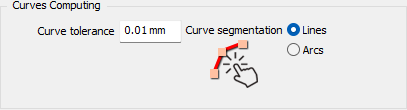
Curve tolerance = 0.01 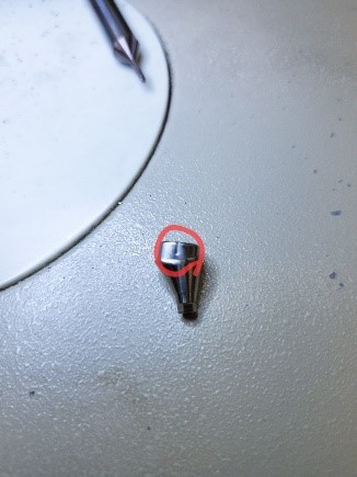
|
Curve Tolerance = 0.1 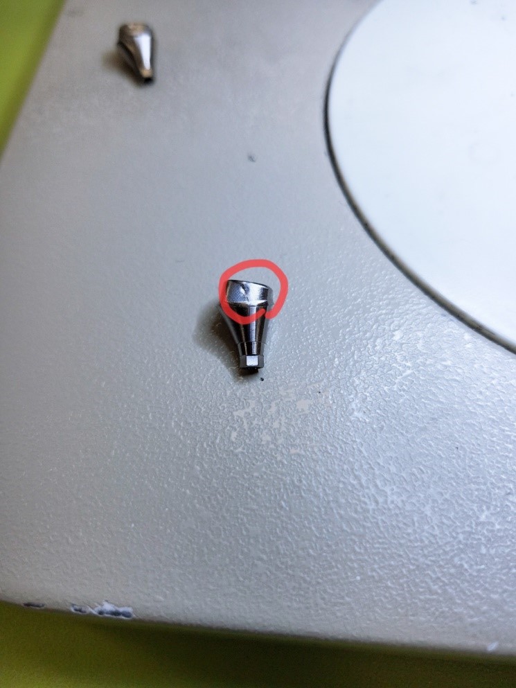
|
Edit Drilling OPERATION
|
..\opelist\casm\02_Drilling 
|
|
Right click to have the menu then “Strategy Edition” 
|
Click on the Icon in red 
|
|
Change your NC codes – then save it 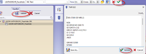
|
Save the file in: ..\opelist\casm\02_Drilling |
Edit Connecting Area OPERATION

|
..\opelist\casm\08_Connecting Area 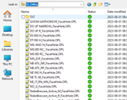
|
|
Right click to have the menu then “Strategy Edition” 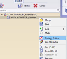
|
Click on the Icon in red 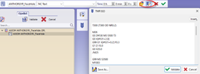
|
|
Change your NC codes – then save it 
|
Save the file in: ..\opelist\casm\0 8_Connecting Area |
Change TOOL - Process will be change if no MTE
1 – Create your new tool in the DATABASE
2 – Inside MTE LOAD your tool
3 – Save FMO
4 – New file to check if tool is in the machine
5 – Edit OPL back turning and change tool (you can replace previous OPL or create new one)
Follow video!
V6.07.207
-
4XS Toolpath = ToolPath is more smooth, rotary speed of S1 is constant, so we can use 0.01 as tolerance
-
Minimum Diameter for protection of the connectic area