
9 important Step (with some abutment some steps are not mandatory, or are done automatically by the APP):
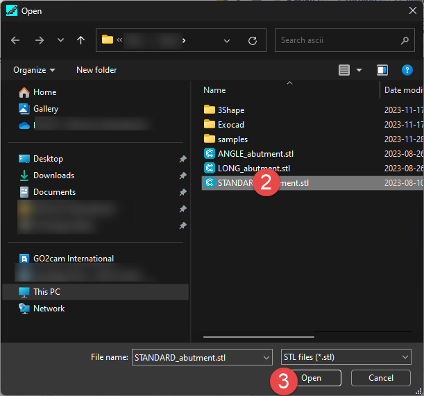
1 - load STL File
2 - Hole on Z axis (rotary axis)
3 - Align according to reference point
4 - Set Drill and Connectic Reference
5 - Set emergency point
6 - Set Reworking Area if needed
7 - Set Face milling area
8 - Calculate
9 - NC file creation
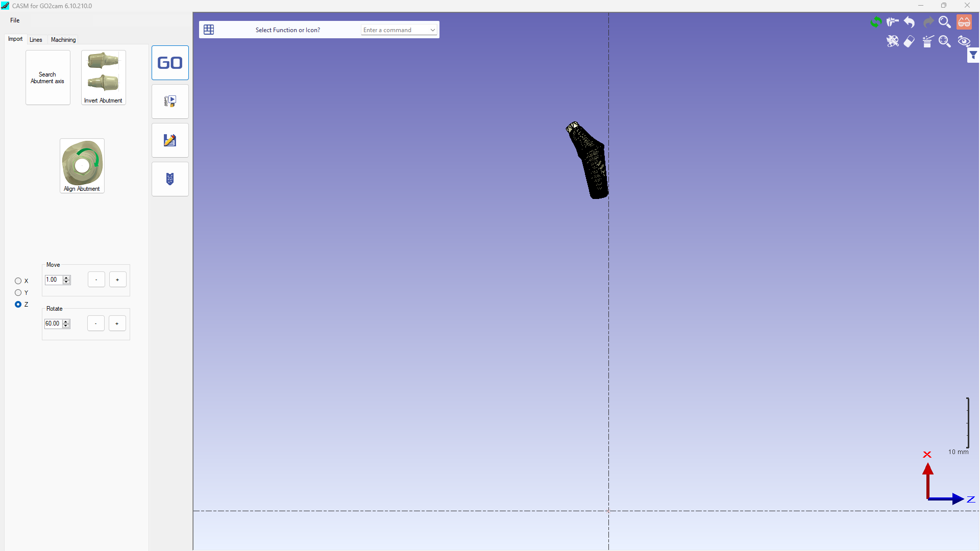
1 - load STL File
2 - Hole on Z axis (rotary axis)
In most of case this step is done automatically by the APP.
However, sometimes according to CAD configuration, CASM APP cannot find the hole automatically.
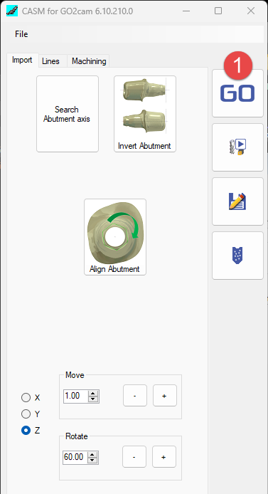
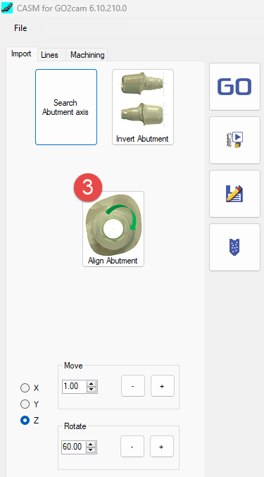
in this case we must use 'Search Abutment Axis' function (take a few seconds to find the hole)
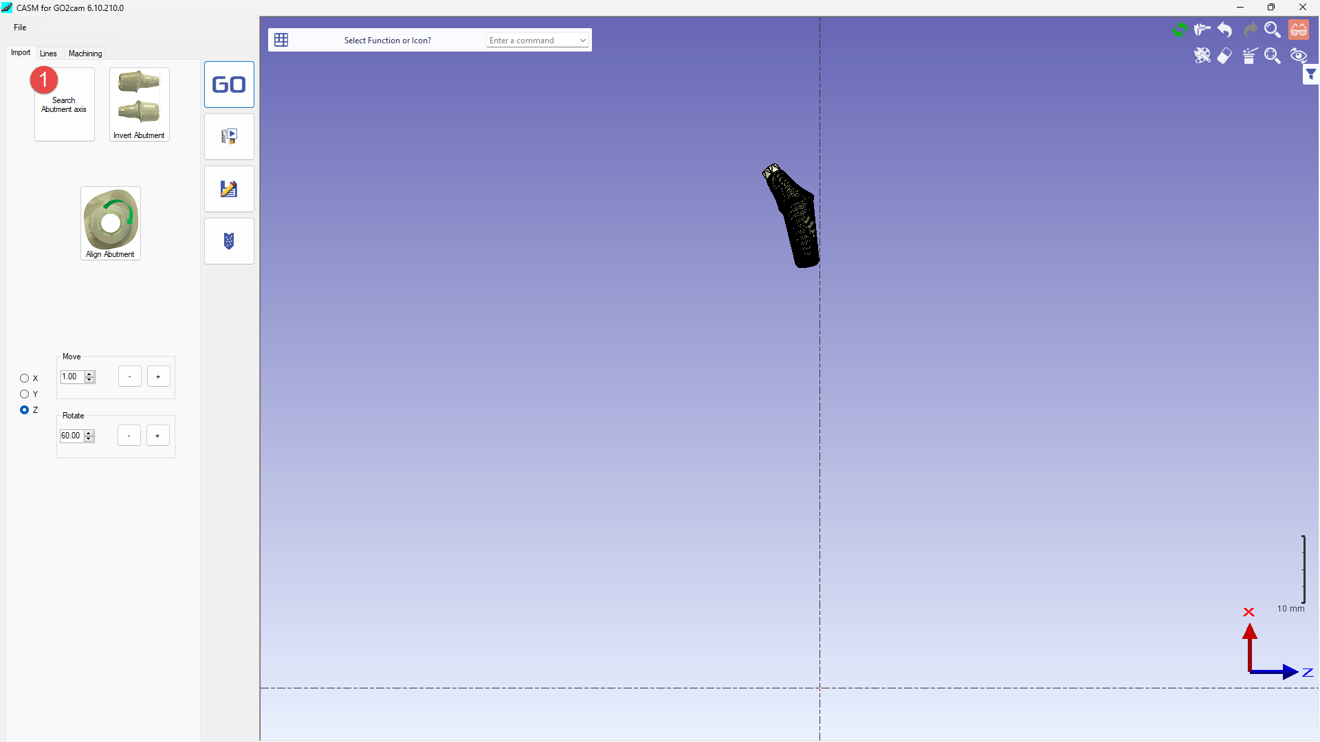
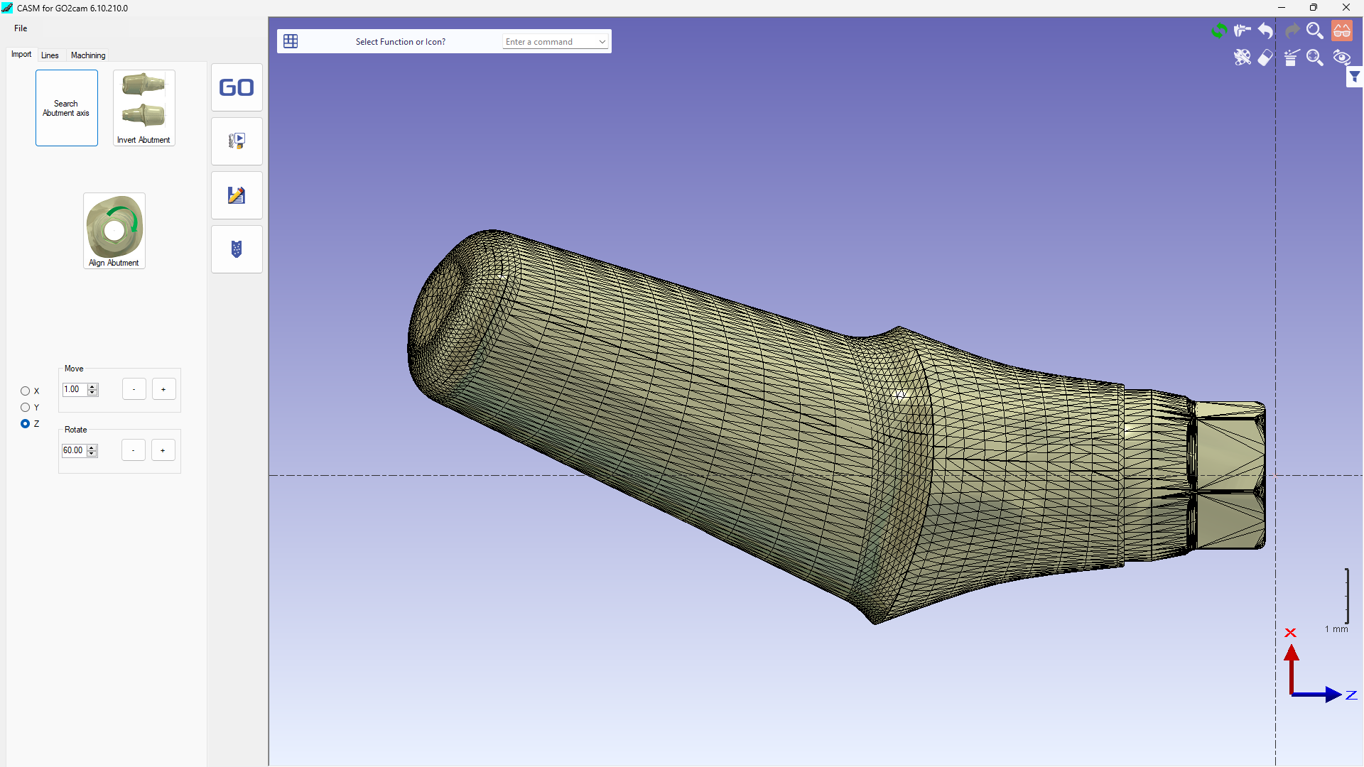
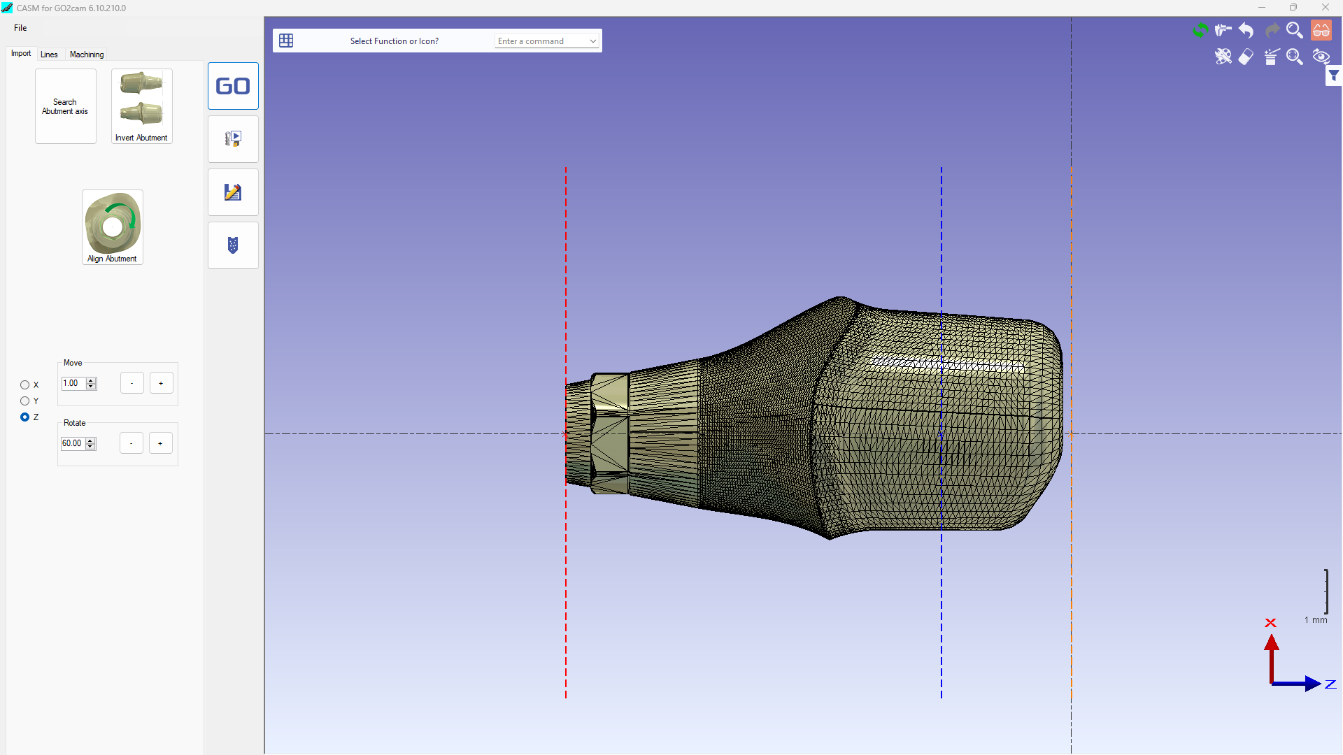
User must check Z direction of abutment.
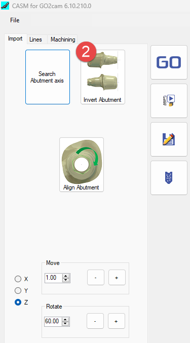
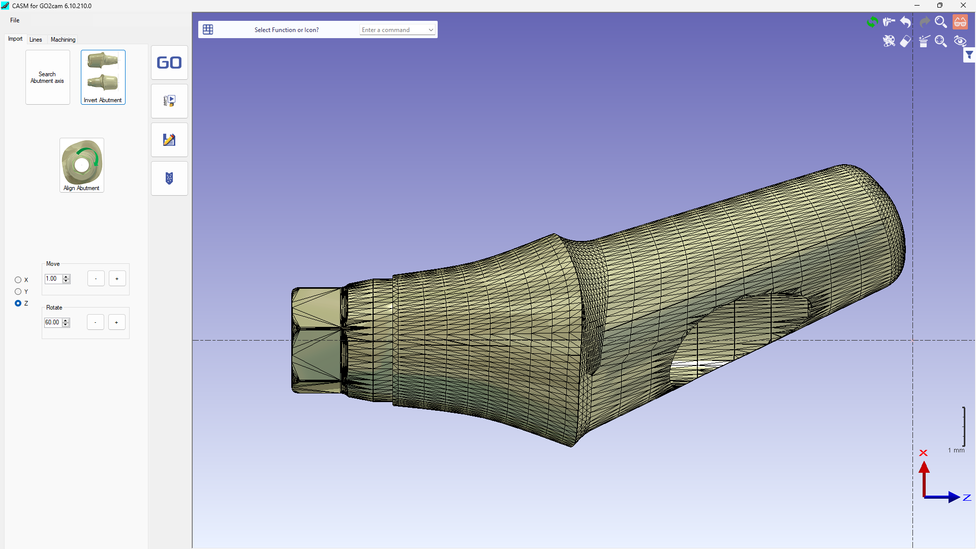
Connectic area must be on LEFT side. If the workpiece is on the wrong side, use function 'Invert Abutment' to adapt.
3 - Align according to reference point
|
1 - Click on the Hexa 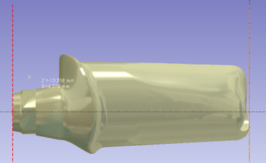
|
Click on 2 points to define horizontal 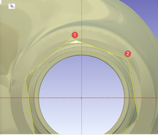
|
According the machine tool, if milling tools are along the X or the Y we can set default value from parameters menu
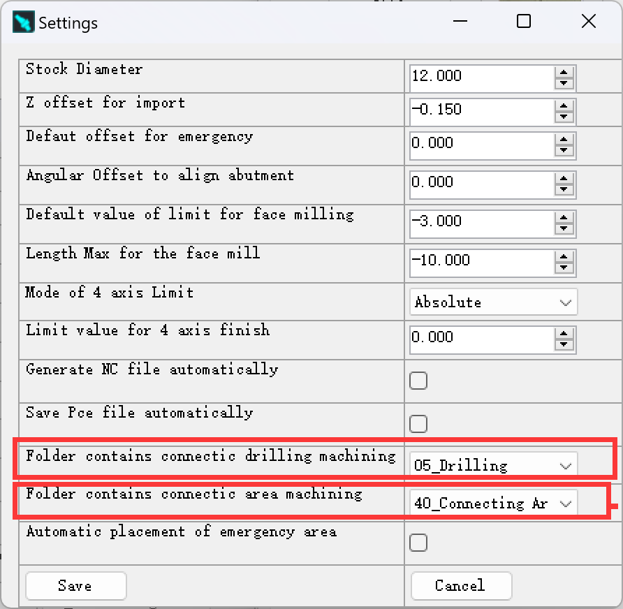
4 - Set Drill and Connectic Reference
Click at ‘Parameters' in menu 'File’:
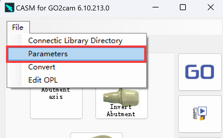
We will enter the setting page of parameters and change the setting if necessary.
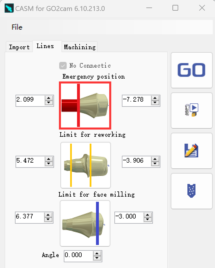
5 - Set emergency position
We can create a vertical line in red color by the function of 'Emergency position'.
A cylinder in read will be created from this position to protect connectic.
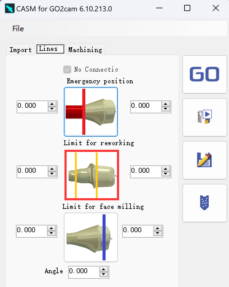
6 - Set Reworking Area if needed
If needed, we can create a vertical line in orange color by the function of 'Limit for reworking'.
A working area of rewoking operation will be defined between this line and margin line.
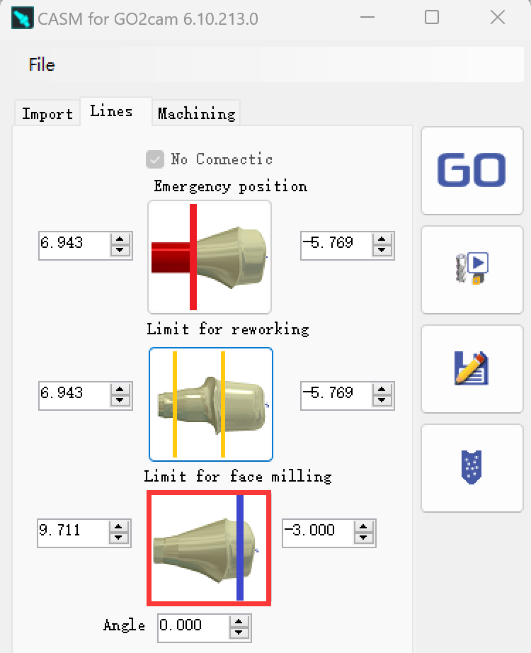
7 - Set Face milling area
We can create a vertical line in blue color by the function of 'Limit for face milling'.
The toolpath of face milling will be stopped at this line.
8 - Calculate
When the parameters and limit positions are set, users can enter in tab ‘Machining' and click at button 'Apply machining’
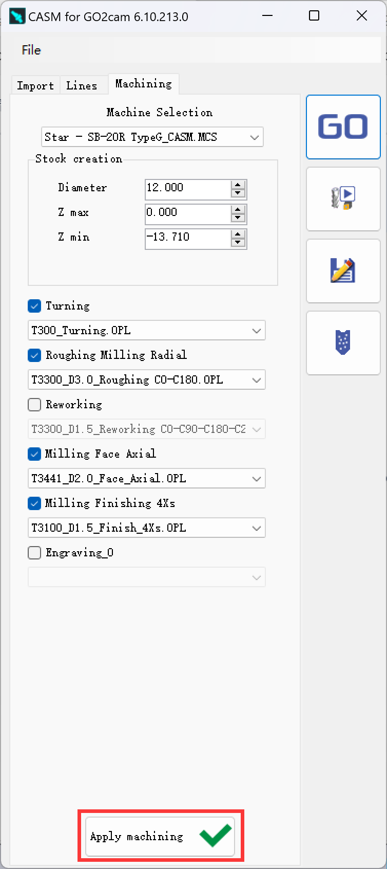
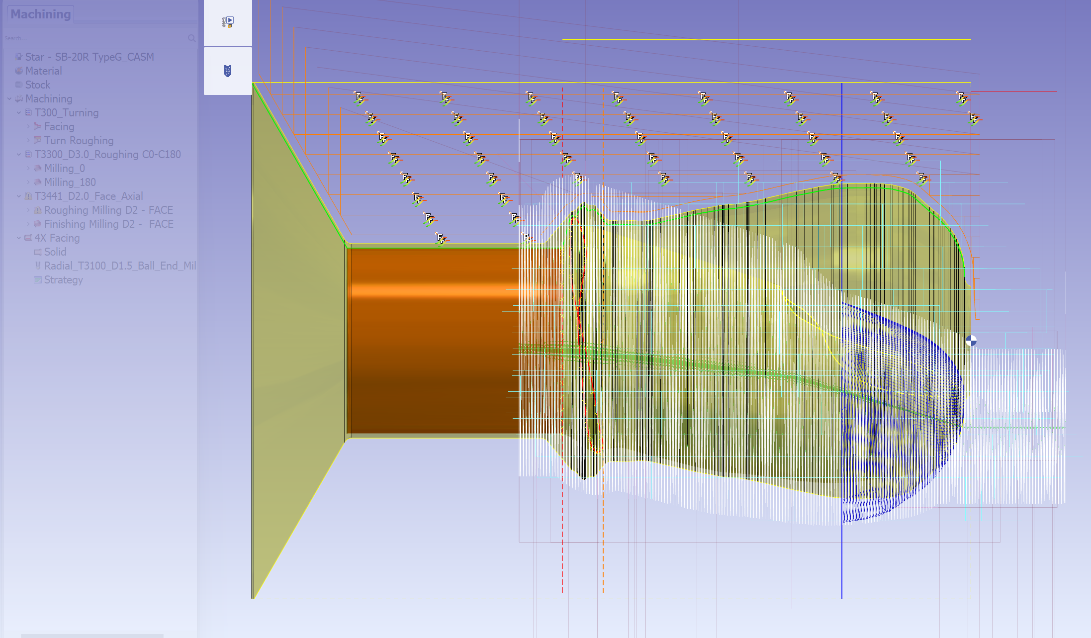
The toolpath will be calculated in a few seconds.
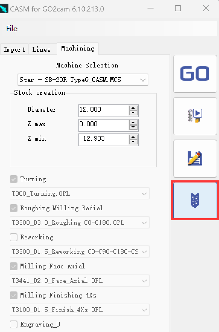
9 - NC file creation
Click at the button 'NC output' to generate and output NC file.
The NC file will be generated and output in a few seconds:
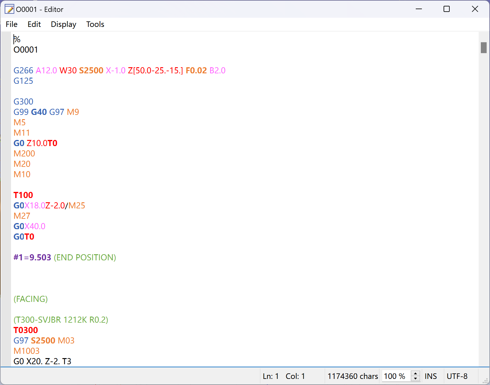
The NC file will by default be saved at the folder 'Iso' in the installed directory of your CASM.
Users can directly edit the NC file in the editor and then save.