
|
|
GO2cam provides a function that allows users to quickly create components—such as clamps or fixtures—based on 2D sketches or 3D geometry. This is useful for integrating symbols into the machining environment without manually defining every detail. |
|
|
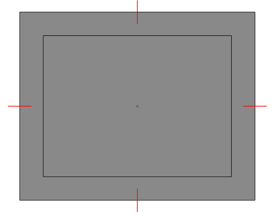
To create a component from 2D or 3D elements, begin by drawing the necessary geometry—such as four 2D line segments or a 3D solid—at the intended location (e.g., where a clamp’s claws will sit). (As demonstrated in Image 1)
|
|
|
|
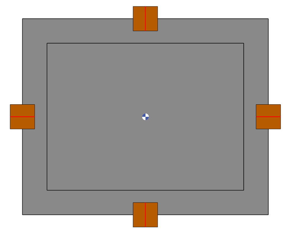
Then navigate to Milling>NC File > Component Creation from 2D or 3D Elements. In the dialog(Image 2), specify the component’s dimensions, configure collision detection as needed and select the relevant geometry. |
||

|
||
|
GO2cam will convert the selected wireframe or solid into a component symbol.
You can hide or change transparency of the symbol by clicking in the Display bar. |
|
|
|
||