
Introduction

|
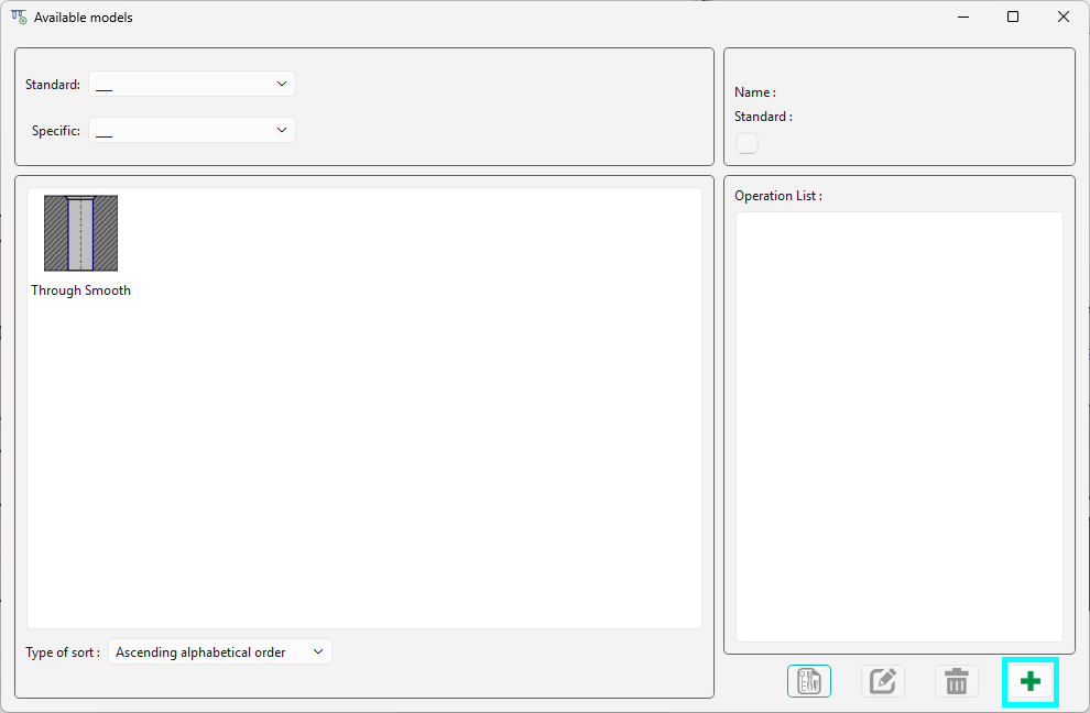
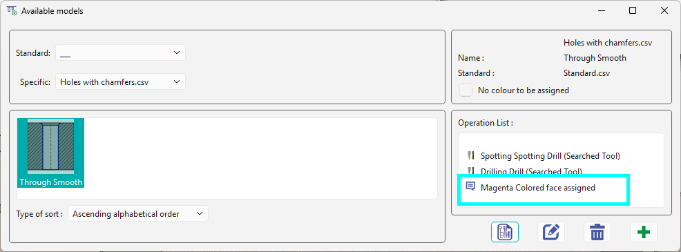
The Users Holes Management command enables the creation of new user hole models. On initiating the command, a window will open and any existing models will be available on the screen. You can choose between the Standard and Specific families. To create a new model, click on the Green Plus icon in the bottom right. The creation of a model is done in 3 stages:
|
|
|
|
|
|
Creation of a Model
|
|||
|
|
|

|
|
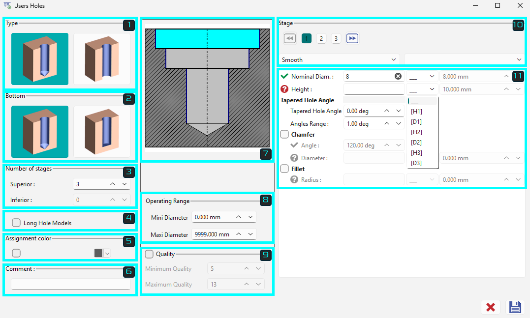
1. General shape of hole
|
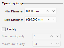
The left half of the dialog gathers the general characteristics of the hole. These information will influence the search of a good model during their application, it is important that these parameters are well defined. Description of these parameters are below.
|
|
||
|
|
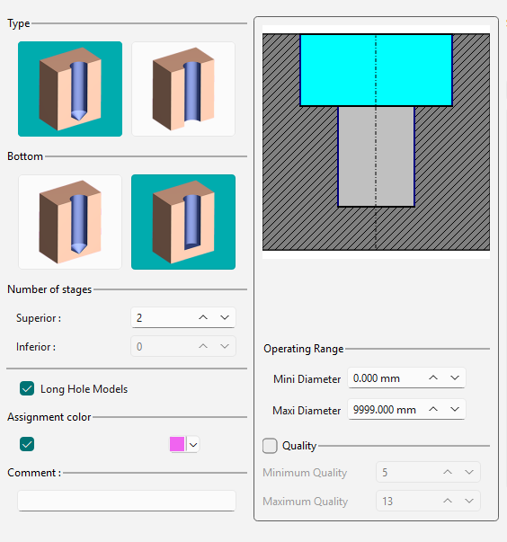
Type of hole: 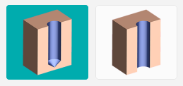
Firstly, choose the type: blind (left) or through (right). |
|
|
|
|
Bottom Type: 
Only for blind hole, select between conical (left) or flat (right) bottom. |
|
|
|
|
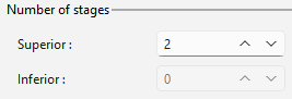
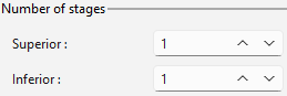
Definition of the number of stages Superior stages refer to levels above the holes. Inferior stages correspond to levels below the holes. Two important points to consider:
|
|
|
|
|
||
|
|
Long Hole Models: sort criteria for the hole’s recognition. By selecting this option, you authorize GO2cam to present this model for a hole that is categorized as “long” during the recognition process. Reminder : during recognition, you have the ability to establish criteria for identifying long holes by specifying the length-to-diameter ratio. The default value for this ratio is 7, which implies that a hole will be classified as long if its length exceeds seven times its diameter. |
||
|
|
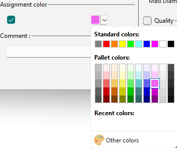
Assignment Color Hole models are assigned a specific color so that they are applied specifically on the same colored faces of a solid. |
|
|
|
|
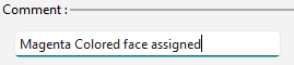
Write any comments on the field. This is displayed in the Available models dialog for the selected user hole model. |
|
|
|
|||
|
|
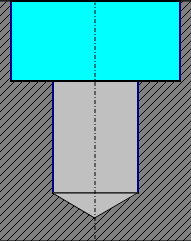
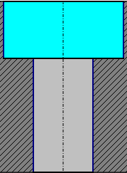
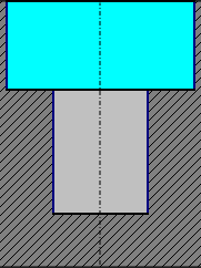
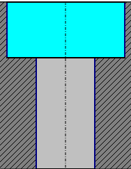
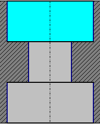
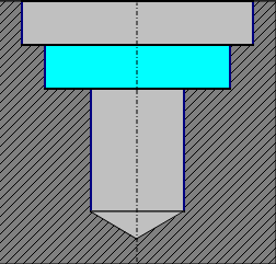
Graphical aid The features of the user hole being created is displayed in the middle of the dialog box. The shape adjusts dynamically while defining the hole parameters. The current stage for which the dimensional parameters are being defined are highlighted by the cyan color. |
|
|
|
|
Below the hole visual, there are 2 criteria relative to the use of models in solid recognition:
|
|
|
2. Define dimensional parameters
|
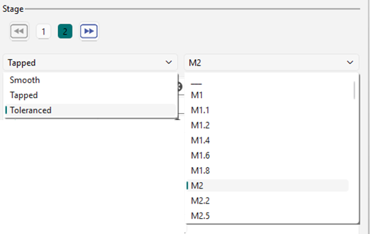
After determining the shape of the hole, proceed to the next step. Model Types: At this critical juncture, the user must decide on the type of model they wish to create:
The right side of the dialogue box is completely dedicated to the dimensional definition of the stage. |
|
||
|
|
Quality of the Stages The stages can be changed by clicking on the numbers or using the forward/backward icons. Each stage can have three different qualities: smooth, counter-bored, and tapped. If a hole requires reaming, it falls under the ‘smooth’ category. If it’s a tapping or a counter-bored hole, you can access the “Standard value” field. Enter the required value for “Mx,” and the corresponding standard values will automatically populate the fields below. |
|
|
|
|
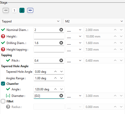
This dialog box remains consistent across all types of holes. If an option has not been selected, it is simply unavailable. First, you need to specify the diameter(s) and height(s) of the stage. Next, define the tapping pitch. Finally, you’ll receive the parameters related to the technological options for the stage:
|
|
|
|
A system of icons enables to identify the status of each parameter: |
|||
|
|
The parameter is validated |
||
|
|
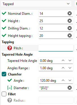
An input of a value has to be done |
||
|
|
An input of a formula (or value) has to be done |
||
Chamfers and fillets
In this context, GO2cam provides the option to create either a chamfer or a fillet, depending on technological feasibility. You can select the appropriate option by checking the corresponding boxes. |
|||
|
|
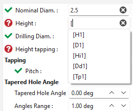
Formula input assistance: Typing “[`” displays a dropdown list of available parameters, facilitating the implementation of formulas in the hole model. |
|
|
3. Define the list of operations
|
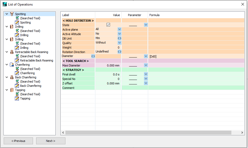
After defining the stages, click “Next” to access the page where you can define the operation list. Regardless of the hole model defined, GO2cam generates a default operation list that you can either validate or modify. For more information about the list of operations: manage and modify the List of Operations. |
|
|
|
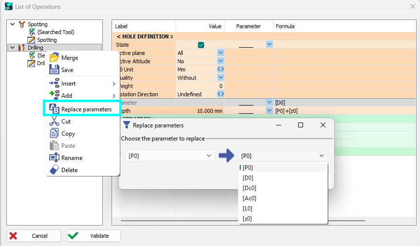
Search and Replace at Users Holes For list of operations, a new function is accessible in a tree pop-up for replacing parameters. |
|
4. Save the model
|
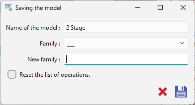
After completing all the necessary steps, remember to save your model. Provide it with a descriptive name and select a family category that will help you organize and locate your models easily whenever you need to apply them. The creation of a new family is done at that moment. Simply enter a new name in the field ‘Family’ |
|
|
|
|
When saving an edited model, users can reset the list of operations with the checkbox. |
|
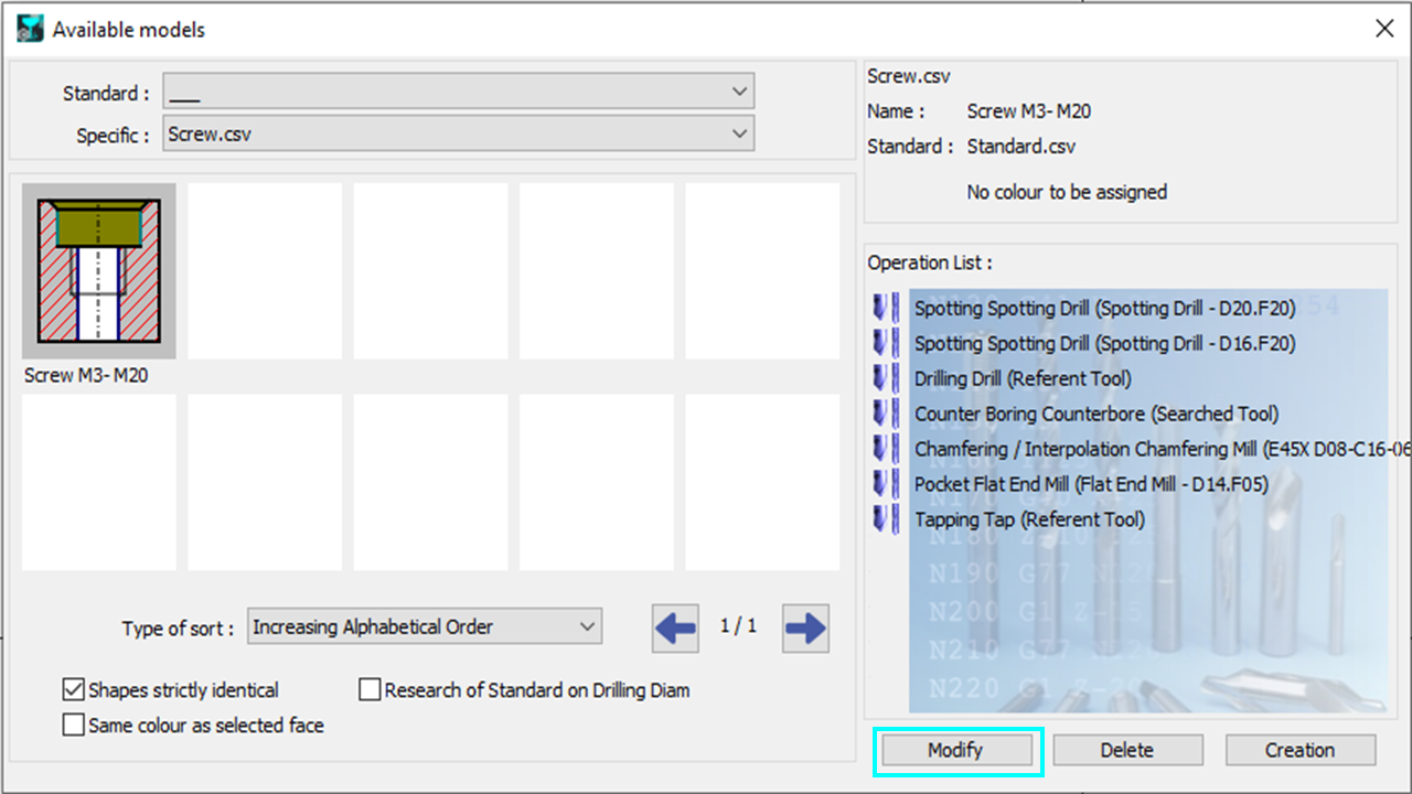
Modify the Model
|
Choose a model in the library of user’s models, then click on Modify. |
|
|
When accessing the Operations List associated with a model, you gain access to all the cycles and tools to be used. The functionalities available during the initial creation can also be utilized for modification purposes:
Additionally, by clicking on ‘Previous’ in the bottom left corner of the dialogue box, you can access the pages for defining dimensional and topological parameters. There are two primary reasons to use model modification:
|
|
|
When you modify the topology of a model in GO2cam, the associated operations lists are reset. This is because the existing operations may no longer be compatible with the new model configuration. By performing this initialization, GO2cam helps prevent serious mistakes and ensures that the model remains consistent with its updated topology. |
|