
Presentation
GO2cam is fully parametric, which means the following can be done:
-
Create family of parts easily,
-
Modify dimensions,
-
Do some prototyping, etc.
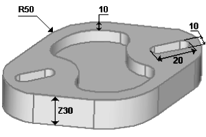
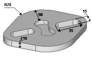
The way the part is designed is very important to make the part modifiable or not: the parallelism, concentricity, tangency constraints are respected if an element is modified, so that all the elements linked to it are modified too.
|
|
Example of a parametric sketch
The aim of this chapter is to introduce the basics of parametric design and explain how to create a family of simple parts using parameters.
In the following example, three dimensions define the geometry of the part:
-
The distance between the centers of the two holes, called L.
-
The diameters of the two holes.
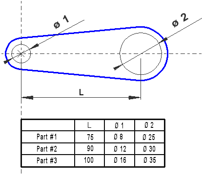
To create a parameterized part, the geometrical elements must be related to each other through geometrical constraints.
These constraints define the relationships between the different elements of the geometry. Examples include:
-
Parallelism — maintains a parallel relationship between two elements.
-
Tangency — maintains tangency between two elements.
-
Concentricity — ensures that two circles or arcs share the same center.
-
Coincidence — ensures that two points or elements share the same position.
The following sections describe, step by step, how to build the part using these constraints and how to modify the resulting geometry by changing its parameters.
The example can also be reproduced directly in GO2cam for practice.
Design
Enter GO2cam and Start the drawing by giving a name to the part: Part #1 for example.
|
Explanation |
Images |
|
Step 1: Click Circle Creation, click on Predefined Circle [1] command. Click the intersection of axes Type 4 (radius) in the dialog, then Enter. |
|
|
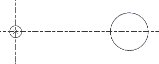
Step 2: Predefined Circle command is still active. Create the center by its coordinates: X=75, Y=0. Type 12.5 for the radius value. |
|
|
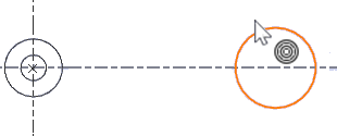
Step 3: Predefined Circle command is still active. Click one hole already created, the contextual cursor indicates concentricity (). Type 5 mm as the offset value. Repeat the same actions with the second hole. |
|
|
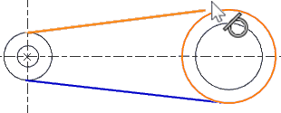
Step 4: Click on Segment command. Show consecutively the two outside circles you just created, the contextual cursor indicates tangency (). Repeat these actions 2 times to create top and bottom segments. |
|
|
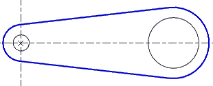
Step 5: Click on Drawing command. Pass the cursor on the two outside circles and click when the automatic GO2cam suggestion is correct. The part is done. |
|
Modification
Once the part has been completed, save the current job using Ctrl+S. Then, select File > Save As… and save the part under a different name, for example Part #2. This preserves the original part while allowing a new variation to be created.
Modifying the Part
-
Select Edit > Edit Element or use the Ctrl+H shortcut.
-
Select the first circle.
-
Modify its characteristics in the dialog zone. For example, change the diameter to 12.
-
Select the second circle and modify its X position to change the L value.
-
Modify the diameter of the second circle as required.
The second variation of the part is now complete.
The same procedure can be repeated to create additional variations of the part.
The geometry must be designed using the appropriate relationships and constraints for the parametric modifications to work correctly. If the part was not constructed according to the methodology described in this chapter, individual dimensions can still be modified, but the complete shape may not update correctly or maintain the intended topology and geometric relationships.
|
▶️ Watch a video on Geometry Parameterizing. 
|