
Overview
Tools can be used for milling, turning, Swiss-type machining, or Wire EDM operations. All tools are described using similar pages, organized into two tabs:
Tool – Contains the tool description and the holder definition.
Options – Contains additional information such as the supplier, reference number, cost, and identification parameters.
At the top of each page, the following common actions are available:
|
|
Reset the page with default values of parameters |
|
|
Save the tool with all modification in Tool and Options pages and the holders if defined. |
|
|
Delete the current tool from library. |
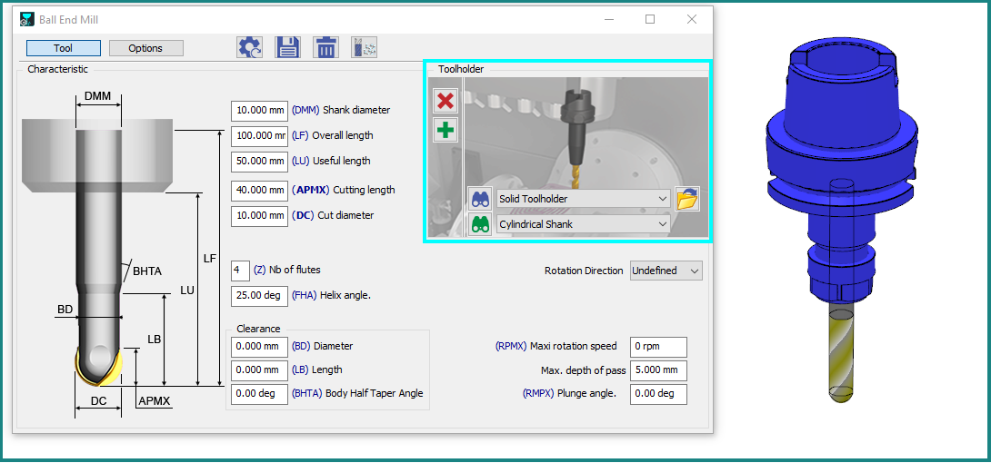
Tool Tab
|
On the Left side of dialog, you can find:
When the tool page is open, the tool remains displayed next to the dialog box. The tool representation is updated in real time to reflect any changes made in the dialog. On the right side of the dialog, in the clear blue frame, are defined the different stages of the tool assembly. |
|
|
|
|
Tools Update Enhanced Any modification in Tool page (diameter value, coolant, specific number) generates modifications in the Technology page of cycles using the updated tool. For instance, cutting conditions are recomputed, coolant numbers are assigned, etc. |
|
Turning: Use of standards for inserts
For turning tools equipped with inserts, a dedicated parameter is available at the top of the tool page. This parameter allows you to define the insert according to its ISO designation. Once the ISO designation is entered, the insert is automatically created with the corresponding ISO-standard characteristics.
Process of Creation of a Tool with its holders.
|
This video demonstrates several key features, including the creation of inserts based on ISO standards and the process of selecting and configuring tool holders. Video workflow:
|
▶️ Watch the video below for an example of this functionality. 
|
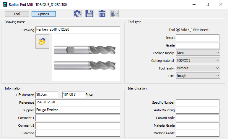
Options Tab
This page does not contain any mandatory information. However, several parameters can be useful for tool management, identification, and production cost estimation.
|
|
|
|
Programming With Holders
|
Effective management of milling tools is crucial for optimal machining. When advising on the milling process and programming, we strongly recommend incorporating toolholders. Every user should utilize toolholders when machining a workpiece due to their significant advantage. Toolholders offer enhanced control over potential collisions. If a toolholder isn't defined during programming, any future collisions involving it won't be factored into the calculations, resulting in an inaccurate toolpath. Therefore, always program with toolholders, specifically for 3-axis milling, programming your toolpath with toolholders is essential for superior collision management. |