
6 important Step (with some abutment some steps are not mandatory, or are done automatically by the APP):
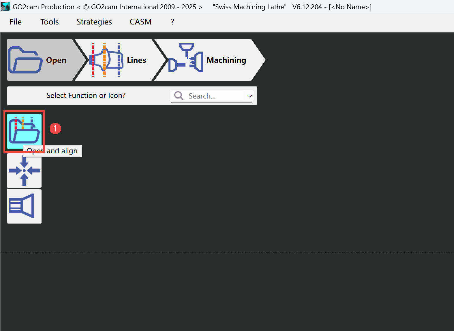
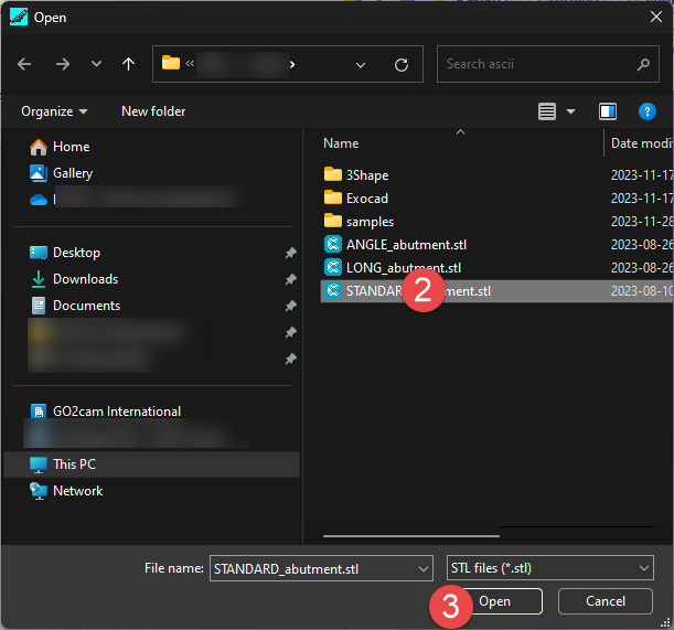
1 - load STL File
2 - Alignment utilities
3 - Set Drill and Connectic Reference
4 - Manual lines placement
5 - Calculate
6 - NC file creation
1 - load STL File
2 - Alignment utilities
Use Alignment functionalities to adapt the spatial attitude of stl.
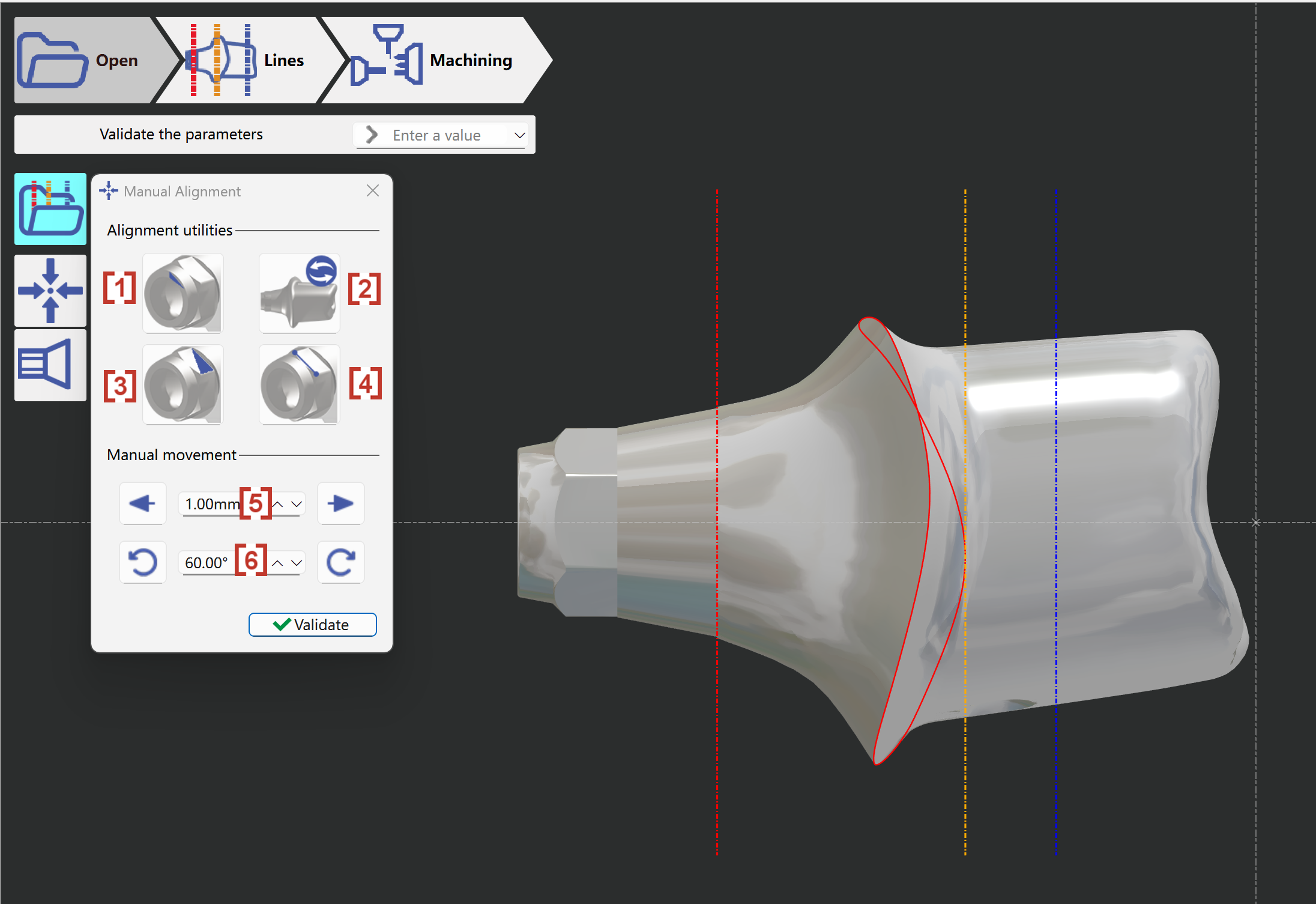
[1] Manual aixs search - If the stl is not with correct axial direction, use this function to automatical get the correct axial direction.
[2] Invert abutment - Invert the direction along axial direction.
[3] Align connectic with face - Align connectic according to a selected surface
[4] Align connectic with 2 points - Align connectic according to 2 selected points
[5] Manual movement along axial direction
[6] Manual rotation along axial direction
in this case we must use 'Search Abutment Axis' function (take a few seconds to find the hole)
User must check Z direction of abutment.
Connectic area must be on LEFT side. If the workpiece is on the wrong side, use function 'Invert Abutment' to adapt.
3 - Set Drill and Connectic Reference
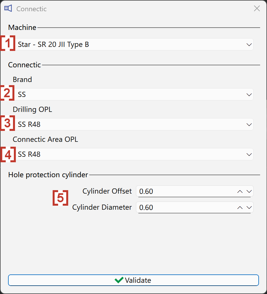
[1] Select the machine tool is necessary.
[2] Select the brand name of the connectic.
[3] Select the drilling strategy
[4] Select the strategy for connectic area
[5] Set the offset and diameter value of created hole protection cylinder
4 - Manual lines placement
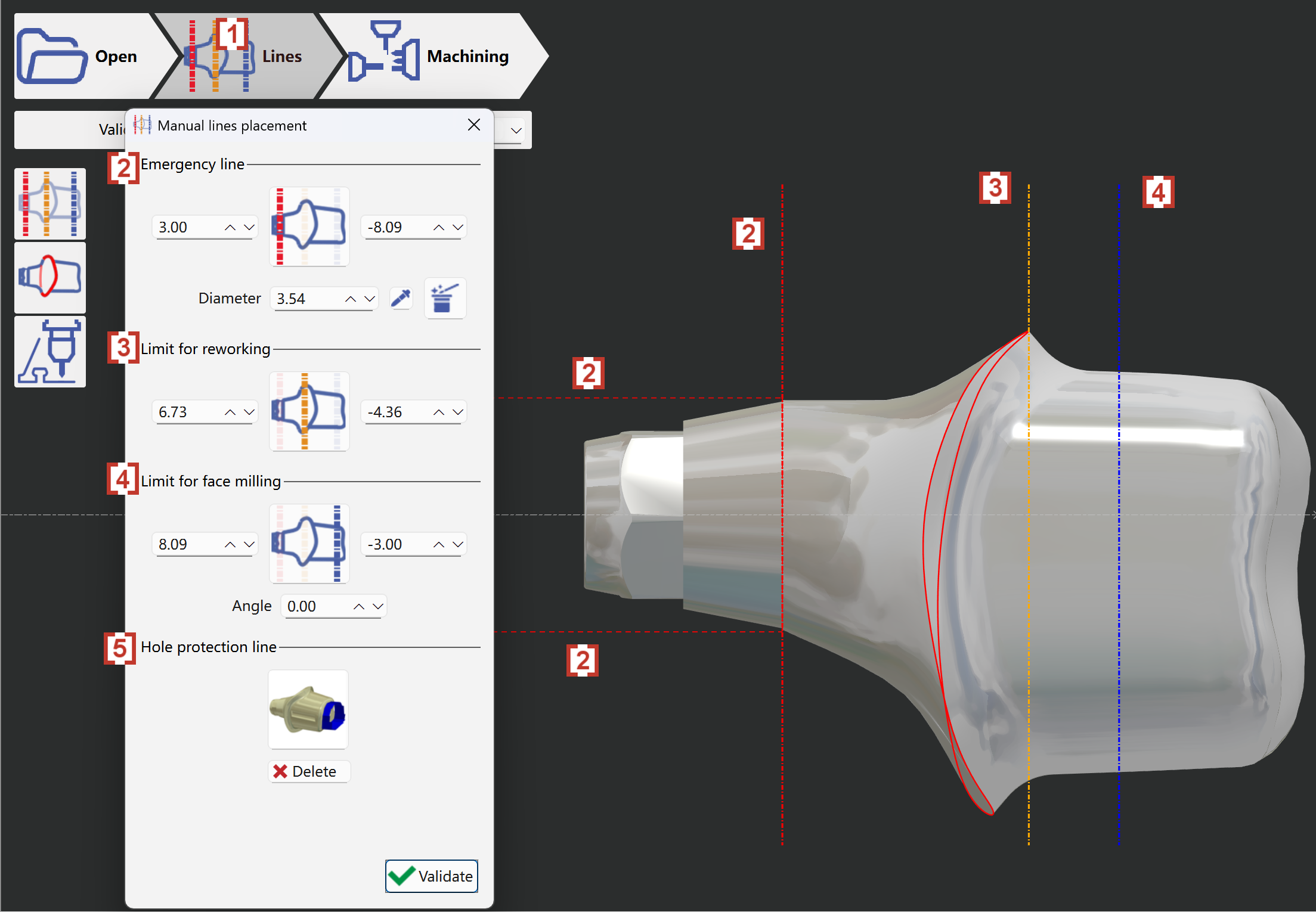
[1] Click at 'Lines' tab to manually create lines of working area.
[2] Emergency line - Define protection area of connectic. Created lines are dashed lines in red color.
[3] Limit for reworking - Define stop area of reworking operations. Created lines are dashed lines in orange color.
[4] Limit for face milling - Define stop area of face milling operations. Created lines are dashed lines in blue color.
[5] Hole protection line - Delete the automatically created protection line if necessary.
5 - Calculate
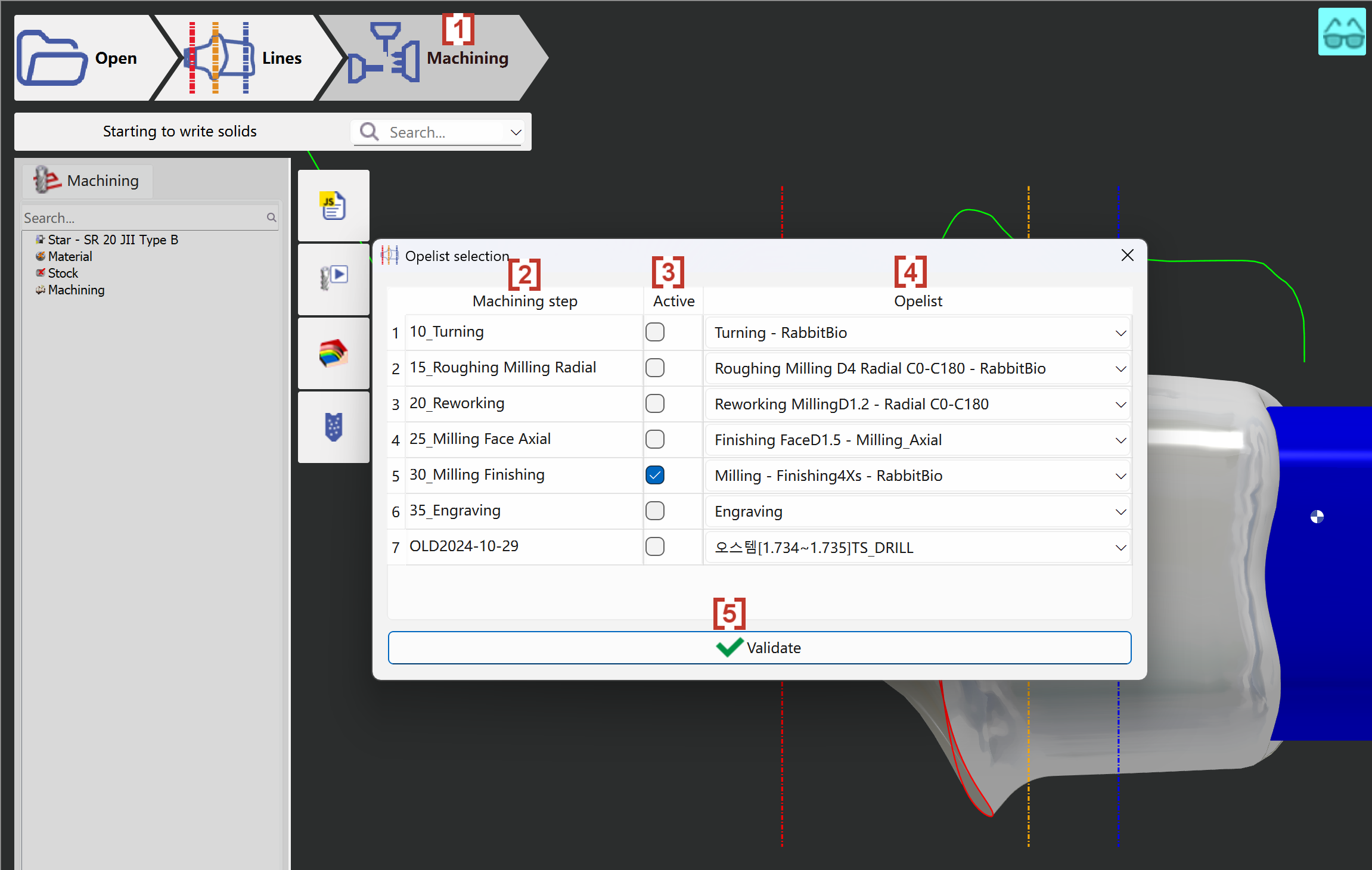
[1] When the manual lines are set, users can enter in tab ‘Machining' to start toolpath calculation.
[2] Machining step - This column displays the operations been applied on the stl.
[3] Active - Use can active or inactive the selected operation accordingly.
[4] Opelist - Select the correct strategy for each operation from the list of available strategies.
[5] Validate - Validate and start the toolpath calculation.
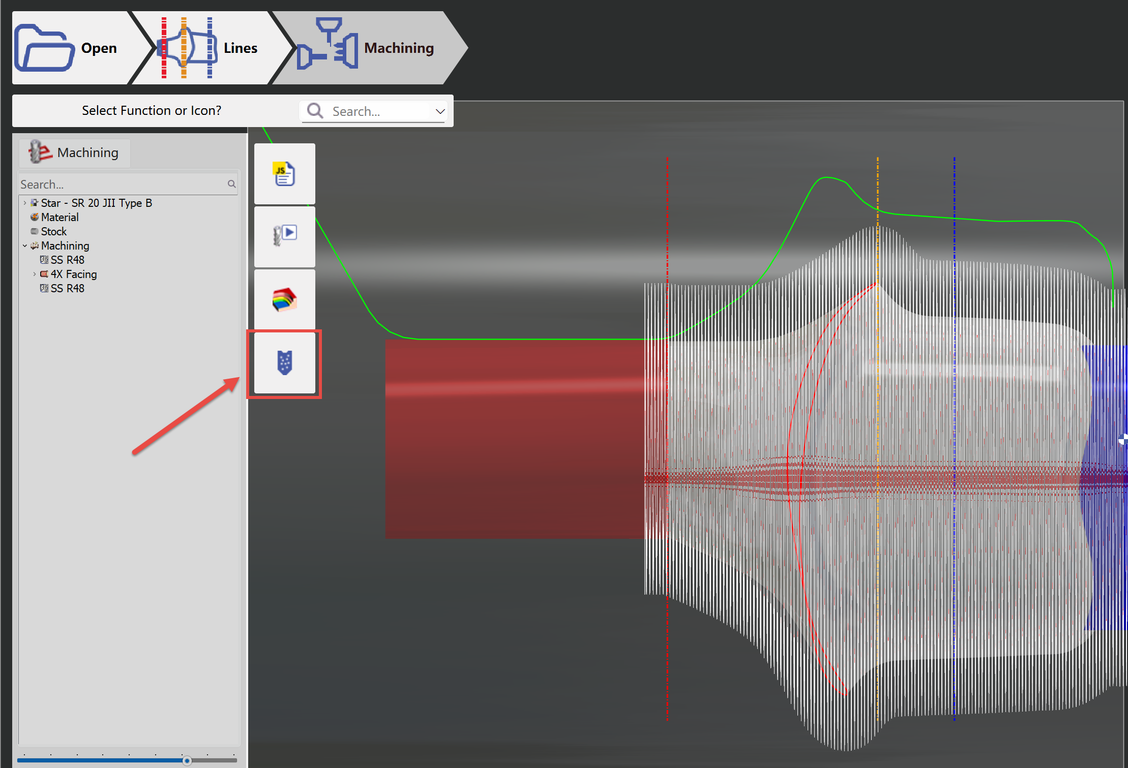
6 - NC file creation
Click at the button 'NC output' to generate and output NC file.
The NC file will be generated and output in a few seconds:
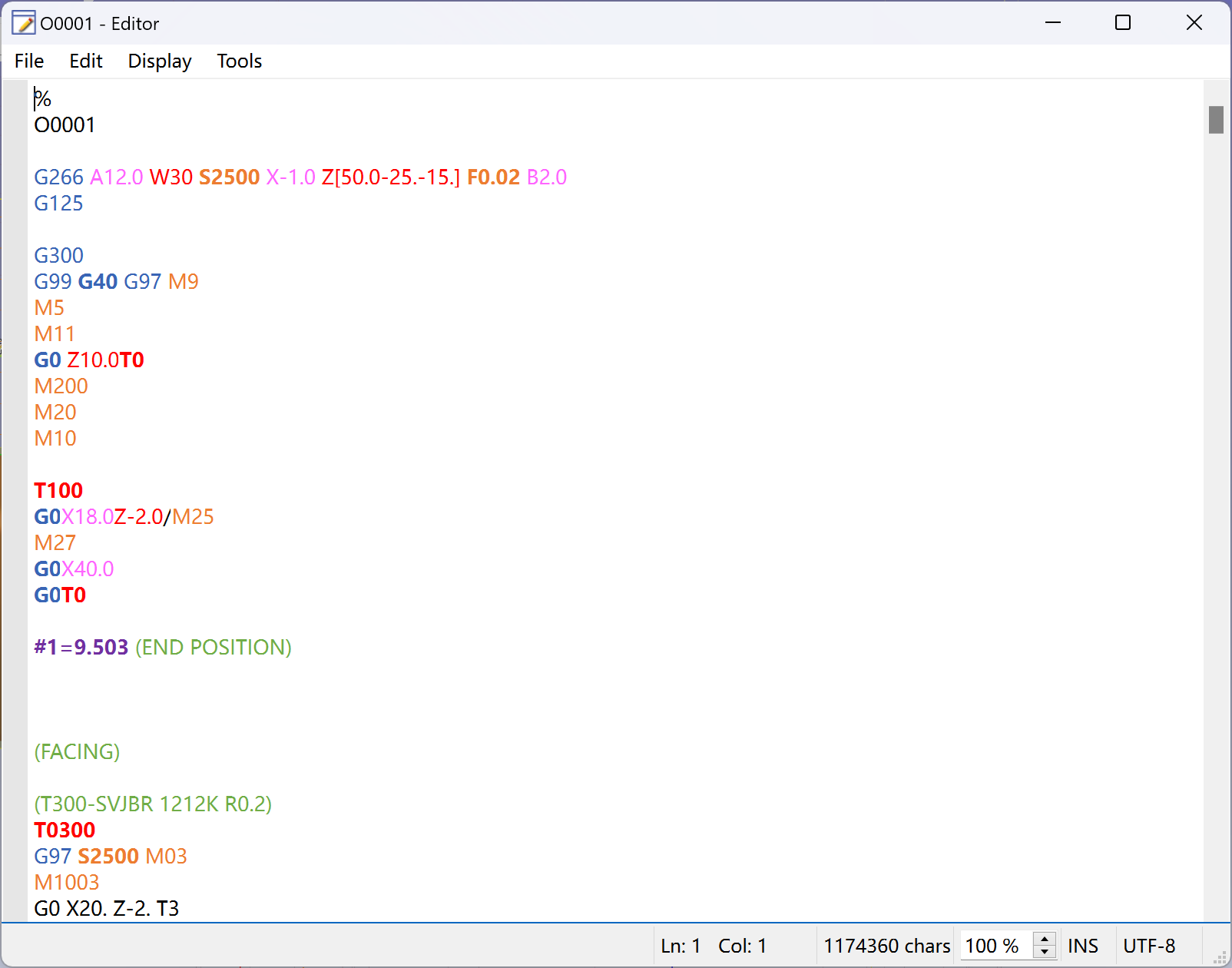
The NC file will by default be saved at the folder 'Iso' in the installed directory of your CASM.
Users can directly edit the NC file in the editor and then save.