
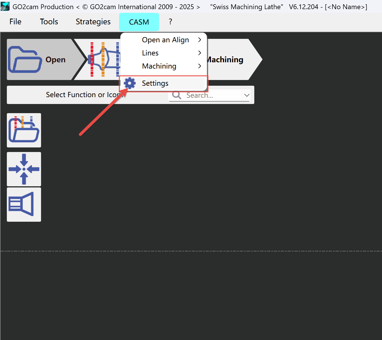
1 - Settings
|
|
|
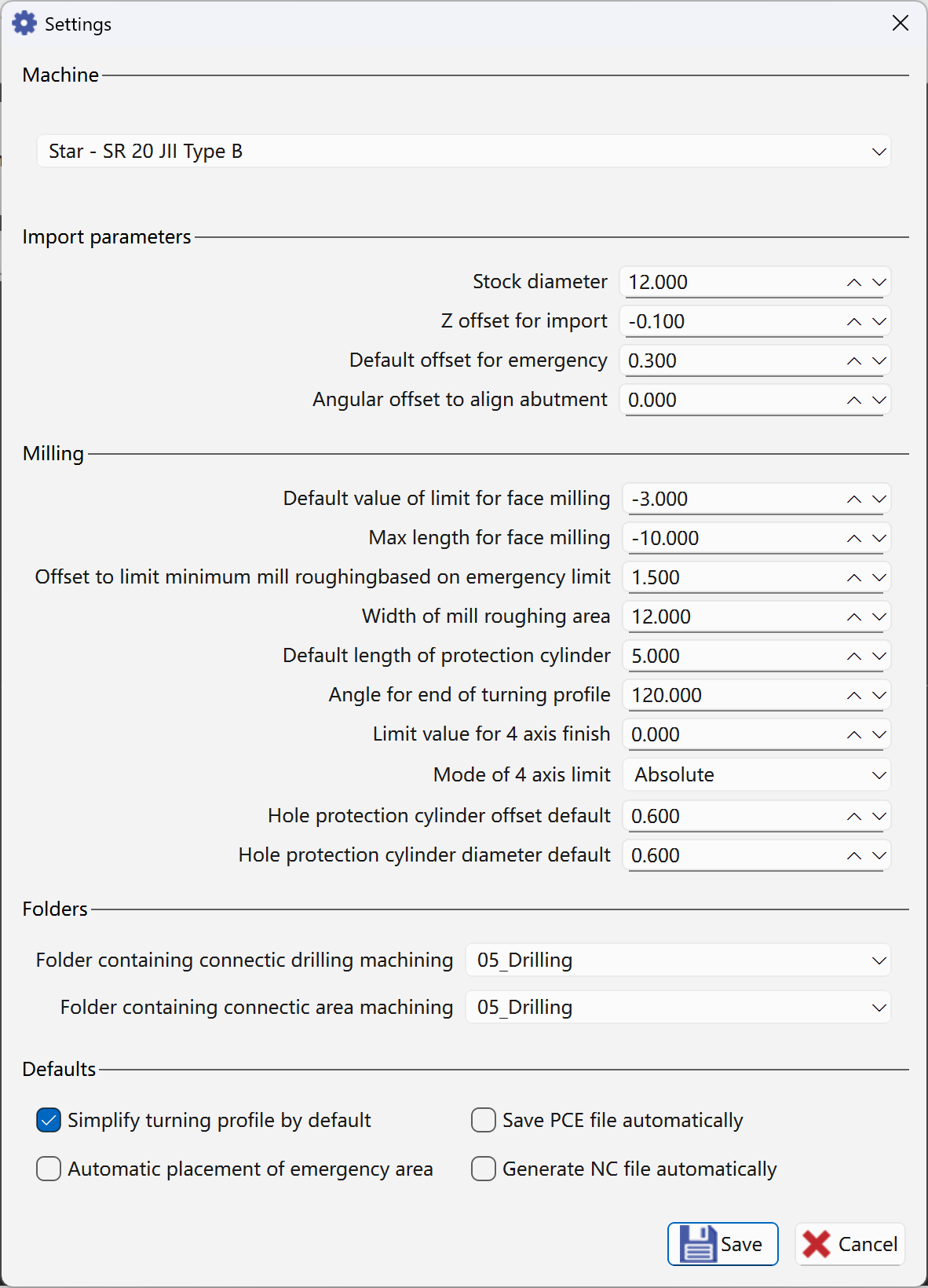
Stock Diameter Change value in Machine file then save the machine |
Size of the bar diameter 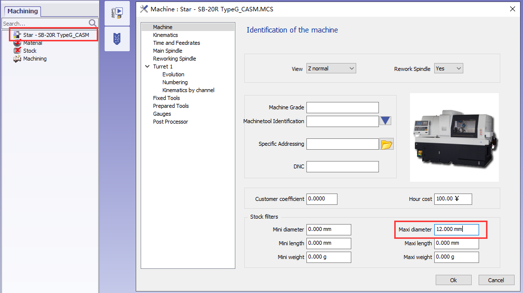
If Abutment is bigger than the diameter we will have error message |
|
Z offset for import |
Placement of anatomic area according the Z 0. 
|
|
Default offset for emergency |
With 2shape file emergency point can be find by application. We can add safety distance to this point |
|
Angular Offset to align abutment |
According the machine tool, if milling tools are along the X value is 0 if milling tools are along Y value must be 90 |
|
Default value of limit for face milling
|
The default distance between the blue line and the X axis. 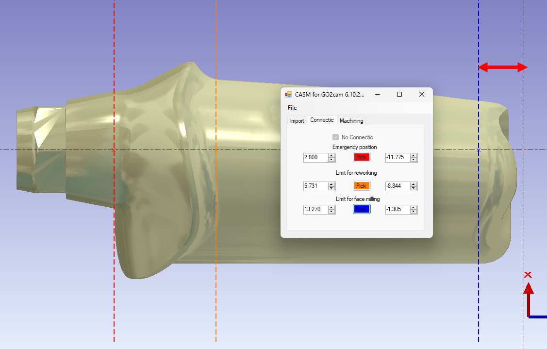
|
|
Length Max for the face milling |
Axial tool have some maximum Z area. 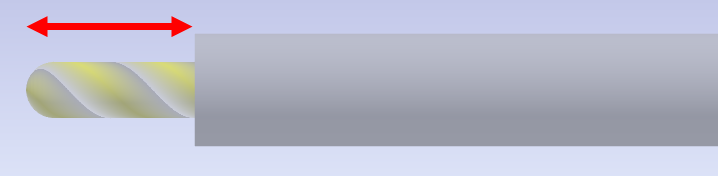
|
|
Offset to limit minimum mill roughing based on emergency limit |
Safety distance of mill roughing |
|
Width of mill roughing area |
Default width of mill roughing area |
|
Default length of protection cylinder |
Default length value of created protection cylinder |
|
Angle for end of turning profile |
Default angle value for end of turning profile |
|
Limit value for 4 axis finish |
In the holes recognition, the cylindric faces which diameter is inferior or equal to this value will be considered as holes |
|
Mode of 4 axis Limit (Absolute / Relative to face Limit) |
Absolute can must be negative value Relative is used to save time and avoid to have 2 tool path on the same area |
|
Hole protection cylinder offset default |
Default offset value of created hole protection cylinder |
|
Hole protection cylinder diameter default |
Default diameter value of created hole protection cylinder |
|
Folder contains connectic drilling machining |
Specify the folder containing the drilling machining |
|
Folder contains connectic area machining |
Specify the folder containing the area machining |
|
Simplify turning profile by default |
Create simle turning profile by default |
|
Save PCE file automatically |
GO2cam file (PCE) is saved inside same fodler as STL file |
|
Automatic placement of emergency area |
Create emergency area automatcially |
|
Generate NC file automatically |
NC file is created after calculation inside same folder as STL file |
2 - Geometry Created
|
Layer |
Comment |
Picture |
|---|---|---|
|
1 |
Stock and 2D Geometry for stock |
|
|
20 |
2D Geometry is used to help create 4-axis solids(Layer 102). |
|
|
101 |
STL file + Connectic area protection + CAP surface on the hole |
|
|
102 |
Solid created on the Face can be used for 4Xs |
|
|
104 |
Facing Line Can be used for facing operation in turning |
|
|
105 |
Parting Line Can be used for parting operation in turning (End of STL) |
|
|
106 |
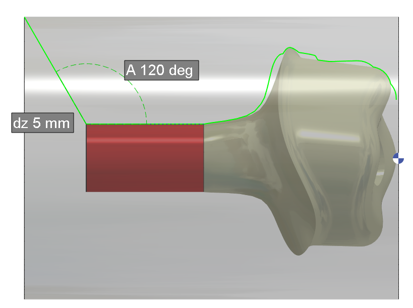
Turning Profil Based on the STL silhouette without Connectic area plus 5 mm and 120deg Length and Angle are fixed inside the APP |
|
|
107 |
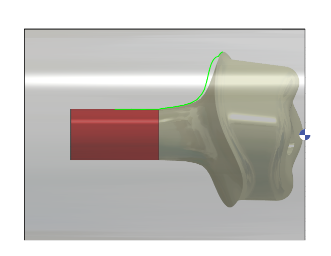
Limitation for 4xs toolpath Can be set from parameters dialog for Z starting End is always at the connectic Area |
|
|
109 |
Turning Profil to machine with a back tool (Some users used this method to avoid rest machining operation between connectic area and Margin Line) |
|
|
112 |
Point to create CAP surface on the HOLE |
|
|
113 |
Curve to create CAP surface on the Hole |
|
|
120 |
Limit for Milling Re-Roughing at C0 and C180 is according Reworking Line (orange) |
|
|
121 |
Limit for Milling Re-Roughing at C90 and C270 is according Reworking Line (orange) and Connectic Area |
|
|
122 |
Limit for Milling Roughing at C0 and C180 is according Connectic Area |
|
|
123 |
Face to limit Axial Milling |
|
|
124 |
Curve to limit Axial Milling |
|
|
160 |
2D geometry is used for Face to limit Axial Milling(Layer 123) |
|
|
206 |
Point to define Connectic area |
|
|
207 |
Point to define Reworking Area |
|
|
209 |
Line to define Reworking Area |
|
|
210 |
Point to define Axial Milling area |
|
|
211 |
Line to define Axial Milling area |
|
|
252 |
Line to define Connectic Area |
|
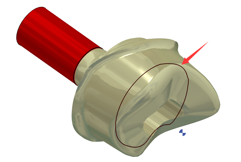
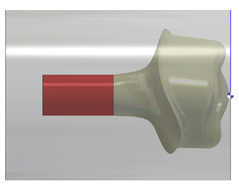
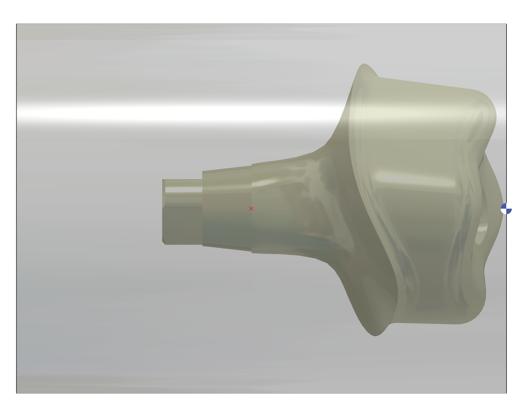
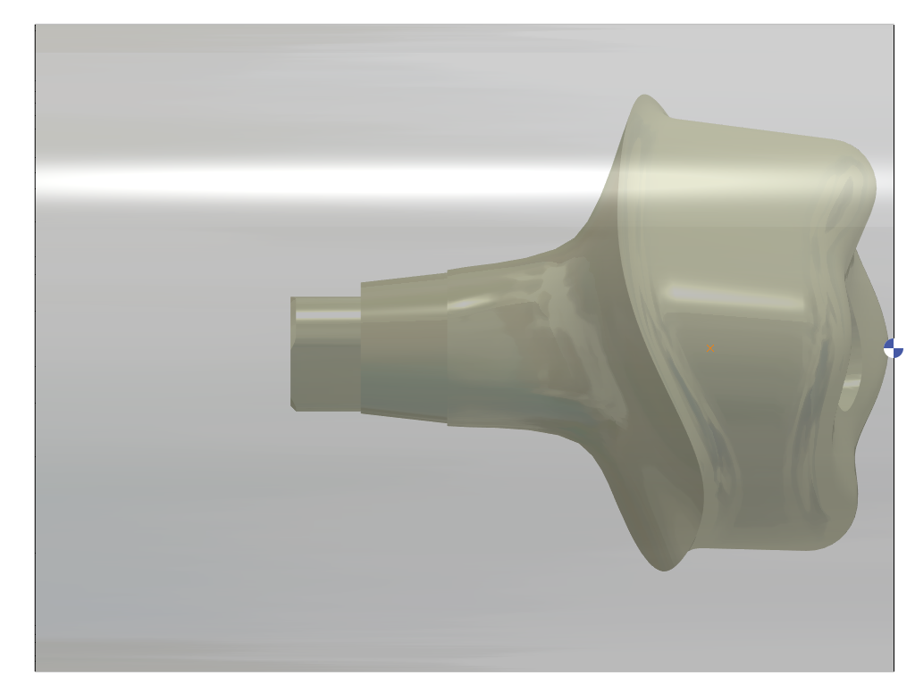
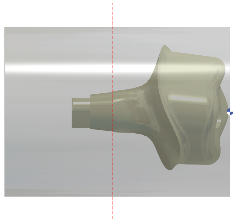
1 – CAP surface (Layer #101)
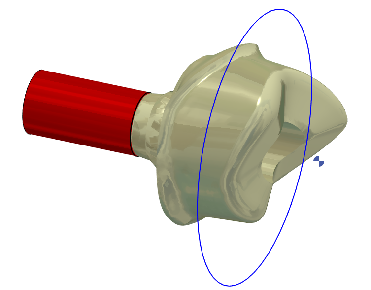
3 – Turning profile (based on the rotary silhouette of the STL file) (Layer #106)
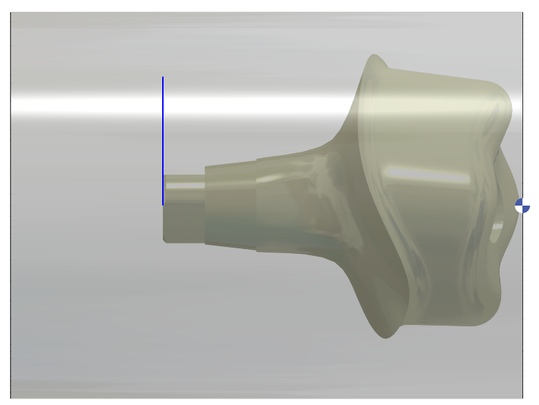
4 – Turning profile is extended 5mm then 30deg until D12mm is created (Layer #106)
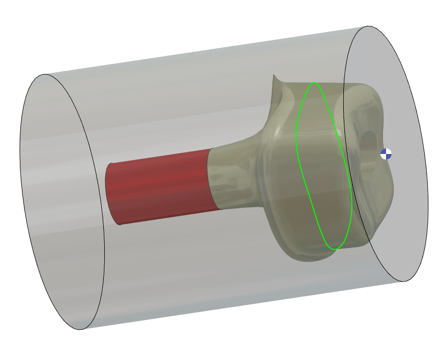
2 – 4axis profile for finishing (Layer #107)
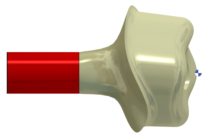
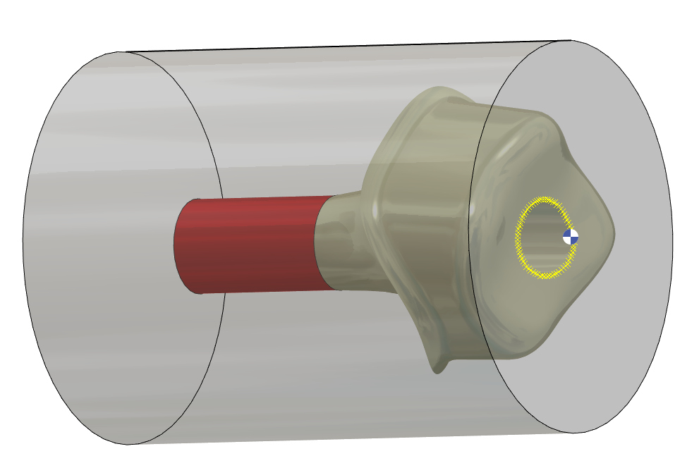
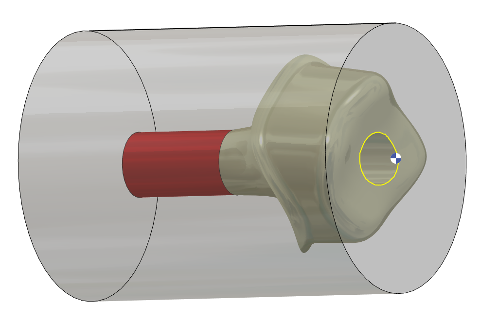
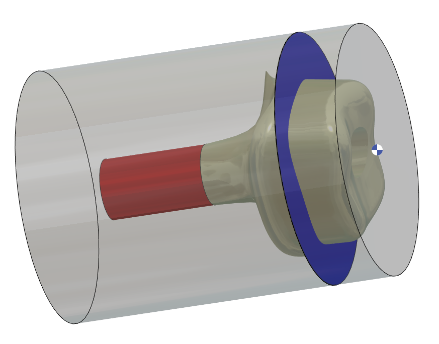
4 – Cylinder around the Connecting Area to protect it during 4Xs (Layer #101)
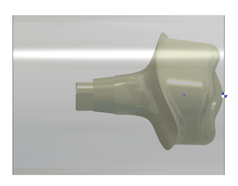
5 – A plane is created every 5°. C0 / C5 / C10 / C15/ C20/ C25….
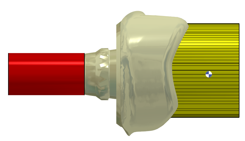
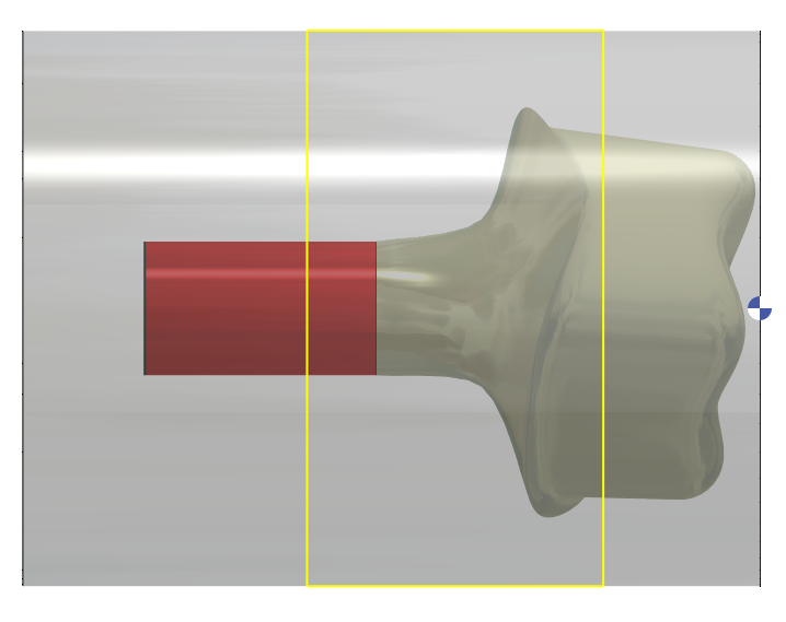
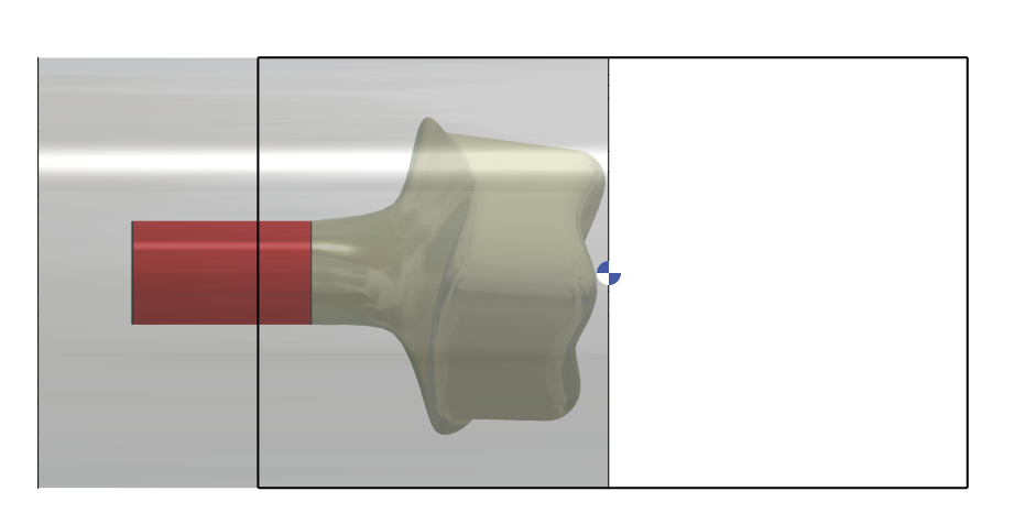
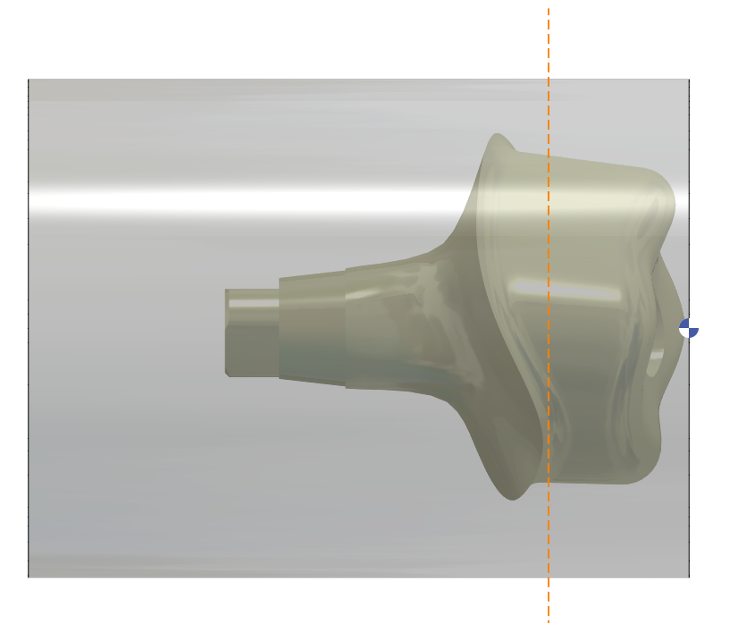
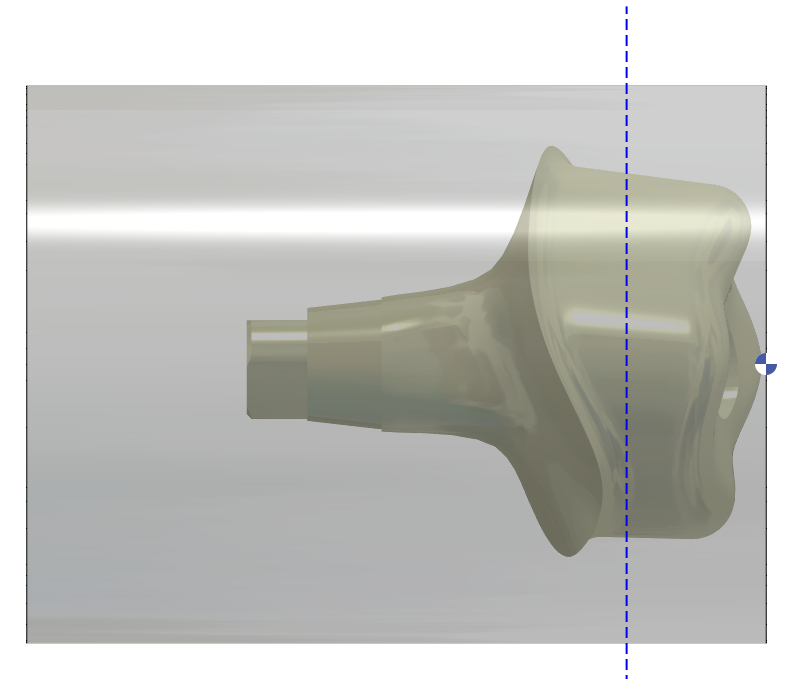
6 – Working area around the STL (can be used in C0 & C180) – area start from 10 mm in front of stl and stop 1.5 mm behind the emergency line (Layer #122)
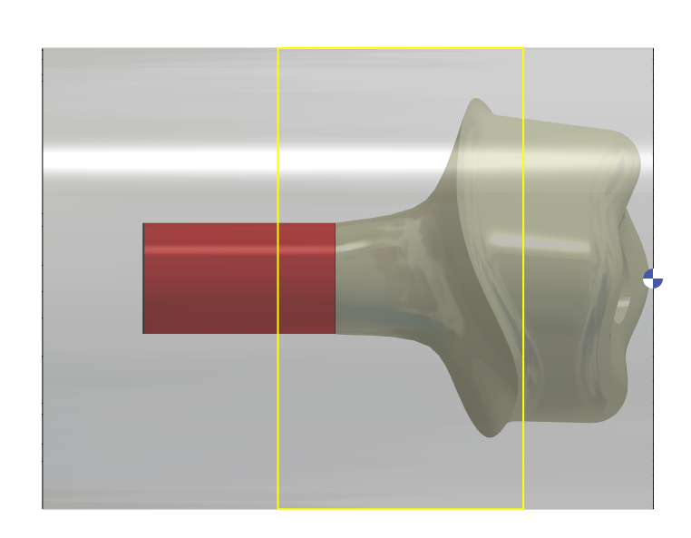
7 – 2 working area near margin and manage by limit for reworking (can be used in C0 / C90 / C180 / C270 - area is according Zmin (1.5 mm behind the emergency line) and Zmax (reworking point) - (Layer #120 & Layer #121)
With V2.10.207 new improvement