
Presentation
|
The workflow can be launched directly using the GO button A simplified ribbon is provided for stock creation and feature analysis of the part. For milling, the steps to position the origin and the vice is also provided. The ribbon is similarly divided into three zones, as shown below. |
||

|
||
|
|
Dynamic ribbon: Guides through all necessary steps required after the design, from stock creation, origin positioning, vice/chuck adjustments and application of machining operations. The user can, at any point in the workflow, revert back to a previous step by clicking on the ribbon icon and carry out modifications as required. |
|
|
|
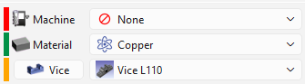
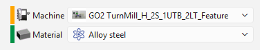
Environment: This zone defines the combination of machine, material, vice and color analysis based on the current module opened by the user. You can access and modify it anytime during workflow steps. |
|
|
|
Validation controls: |
|

|
Validation of the current step and proceed to the next step. Validating the final step completes the workflow wizard and finalizes the computation of the toolpaths. The same is achieved on validating (green tick) through the dialog for each step. |
|

|
Available as a drop down from the main validation button. It allows for automatic validation of default values (preset settings saved from previous workflow operation), quickly going through the steps and computing the machining toolpaths. |
|

|
This button stops and exits the workflow wizard at any point in the workflow steps. All prior setups done in the wizard are saved. |
|

|
Watch a video showing the use of the workflow for a designed part. This example is in the milling machine module and is repeatable for turning and wire-cut EDM. |
|
Environment
|
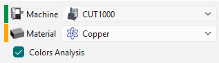
This is usually the first setup that is carried out, even though it can be modified/updated at any moment in the workflow. This section allows to setup the machine and define the material for stock. It provides a complete workflow experience with a programing process with the part and machine setup, just through this ribbon. The drop down list for the machine and material is based on the user database and compatibility. The Color Analysis checkbox, in wire-cut EDM, activates the recognition of color surfaces on the solid and application of strategies based on color. A color code is associated on the left of each category. The representation of the color code are as per below: RED: Nothing is set or defined for the category YELLOW: Automatic preset based on previous settings. Data from the previous operation is saved GREEN: Manual selection has been done. If a Machine or Material has been defined in the software configurations, these are always prioritized and automatically set in the workflow. The indicator is GREEN for this situation. |
|
|
|
|
The Dynamic Ribbon

|
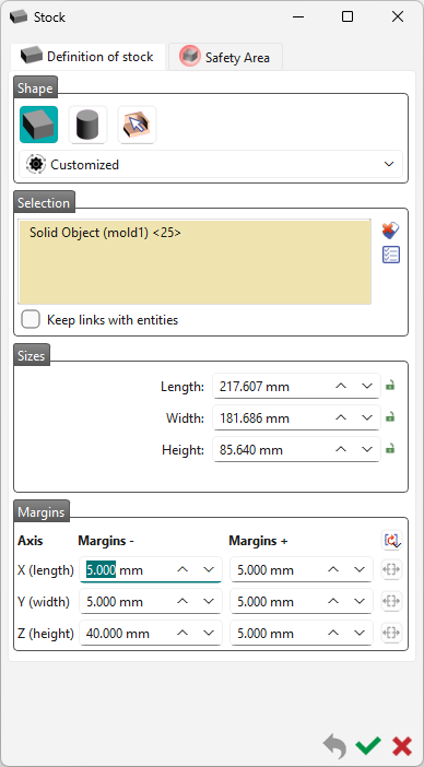
Applicable in all modules! The next step enables to create/modify the shape, the size and the position of the stock. The default stock created is cubic, but you can choose a cylindric shape or a specific solid. By default, the stock is the bounding box of the solid with 5 mm more in the 6 directions X+, X-, Y+, Y-, Z+, Z-. You can modify this value of 5 mm, in the Margins. For the workflow, the default values are those preset in the previous workflow operation. For detailed information on the stock creation, click on the link here. |
|
|

|
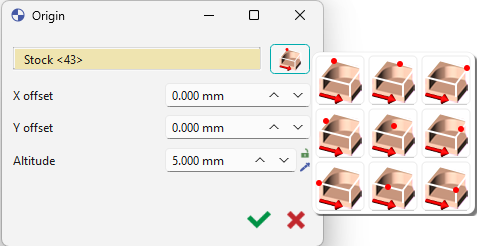
Applicable in milling and wire-cut EDM! There are 2 possibilities for positioning of the origin:
After selecting the point, you can move it on the Z axis by defining an Altitude. By default, the origin is set at the maxi Z of part. An offset on X axis (DX) or Y axis (DY) can also be set according to the reference point. For additional information on the creation of program origins, click the link here. |
|
|

|
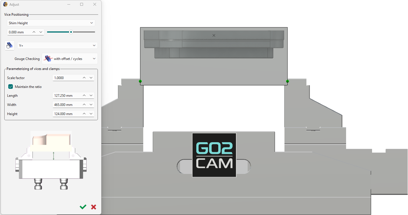
Applicable in milling! If a vice is defined, this step automatically adjusts the stock optimally in it. This diminishes any need for readjustments but the dialog box is still provided for any manual settings. Details about the adjustment settings can be found by clicking the link here. |
|
|

|
|
Toggle the Analyze step off (red) or on (green) to avoid or allow application of cycles computation. Mostly applicable for automatic validation of the workflow. |
|
|
|
|||
|
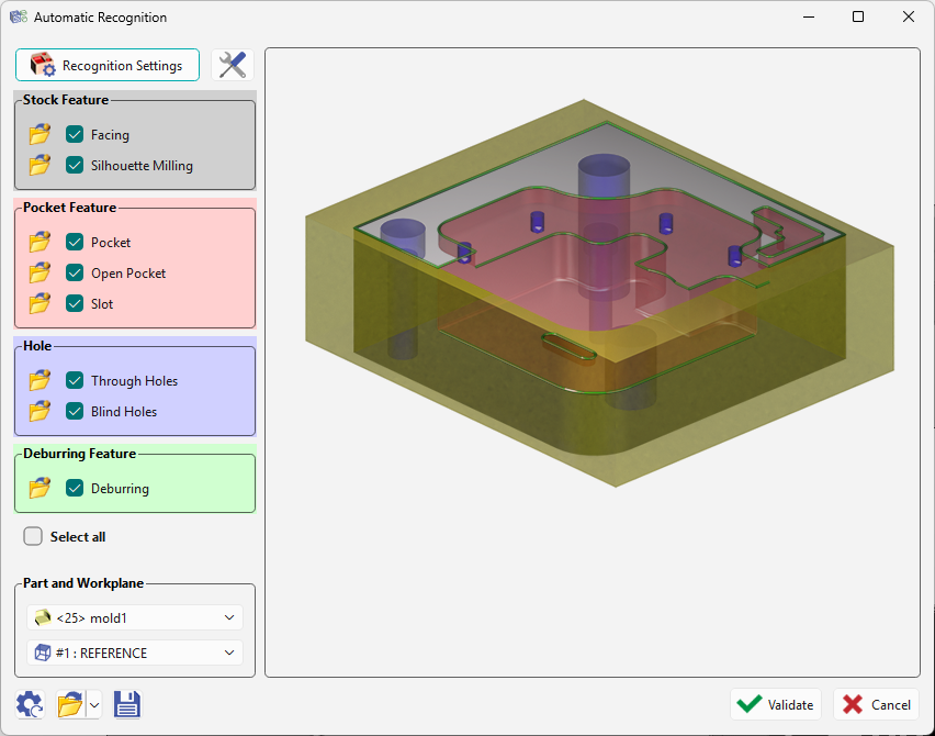
Applicable in all modules! This step launches the automatic recognition of features on the solid for application of machining cycles based on features opelists. This is the final step and upon validation, the machining cycles will be automatically computed and the machined part will be presented. For details about the general machining features, click the link here. |
|||