
Presentation
|
The workflow in wire-cut EDM is launched with the import of a file. Some of the ribbon icons and sequences of operations are dedicated only for this module. The current step is highlighted in teal. The ribbon in itself can be segregated into 3 zones as shown below. |
||

|
||
|
|
Dynamic ribbon: Provides all the steps to proceed with an imported part, up to the application of machining cycles. Some steps may or may not appear, for instance the identity step will only appear if the imported file contains multiple parts. The user can, at any point in the workflow, revert back to a previous step by clicking on the ribbon icon and carry out modifications as required. |
|
|
|
Environment: The zone to define the machine, material and activation of color analysis or not. This can be accessed and modified anytime in the workflow steps. |
|
|
|
Validation controls: |
|

|
Validation of the current step and proceed to the next step. Validating the final step completes the workflow wizard and finalizes the computation of the toolpaths. The same is achieved on validating (green tick) through the dialog for each step. |
|

|
Available as a drop down from the main validation button. It allows for automatic validation of default values (preset settings saved from previous workflow operation), quickly going through the steps and computing the machining toolpaths. |
|

|
This button stops and exits the workflow wizard at any point in the workflow steps. All prior setups done in the wizard are saved. |
|
|
Watch a video showing the workflow in wire-cut EDM in action. |
|
Environment
|
This is usually the first setup that is carried out, even though it can be modified/updated at any moment in the workflow. This section allows to setup the machine and define the material at any point during the workflow. It provides a complete workflow experience with a programing process with the part and machine setup, just through this ribbon. 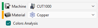
The drop down list for the machine and material is based on the user database and compatibility. The Color Analysis checkbox activate the recognition of color surfaces on the solid and application of strategies based on color. Watch a video about the application of Color Analysis on the right. |

|
|
A color code is associated on the left of each category. The representation of the color code are as per below: RED: Nothing is set or defined for the category YELLOW: Automatic preset based on previous settings. Data from the previous operation is saved GREEN: Manual selection has been done. If a Machine or Material has been defined in the software configurations, these are always prioritized and automatically set in the workflow. The indicator is GREEN for this situation. |
|
The Dynamic Ribbon

|
This is the first step in the ribbon, launching the workflow, on loading a part, either through the GO button or a drag and drop. This opens the Solid import dialog; for more details on that, click the link here. If a single part is in the imported file, a bounding box is generated to envelop the solid. At any point in the workflow process, the user can click on the Import icon to revert back and relaunch the import operation. |
|
|

|
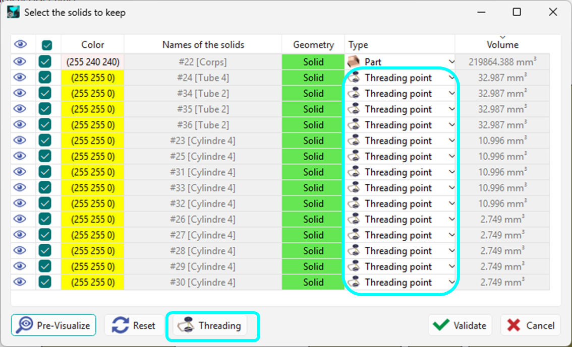
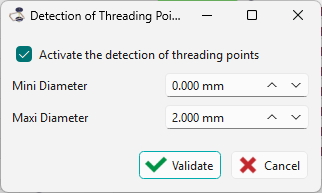
This step is only available if several CAD files are imported at the same time or the imported file contains multiple solid parts. It launches the dialog for the treatment of the list of solids. Recognition and distinction can be made between parts, stock, symbols and threading points. Specific to this module is the ability of the software to automatically detect small, solid cylindrical components as threading points and convert them as such. Access to the dialog is available through the Threading button at the bottom of the box. The checkbox for 'Activate the detection of threading points' must be activated to implement the detection algorithm. A range of diameters can also be defined to limit the detection range. |
|
|
|
Watch a video below showcasing the detection algorithm during import. |

|
||

|
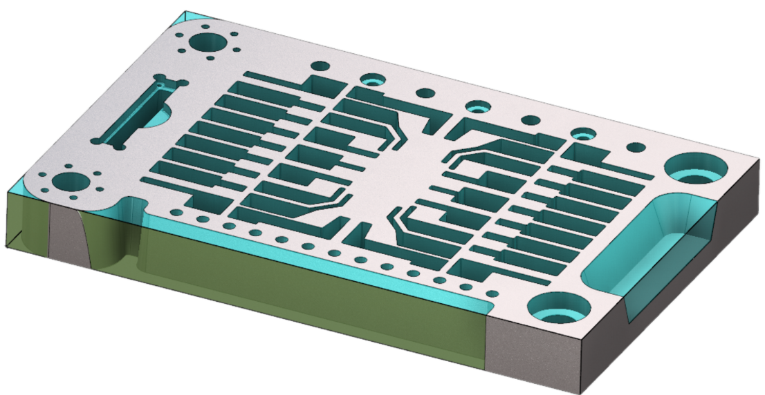
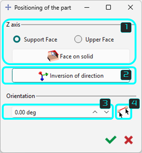
This step is the positioning of the solid and the stock on the Reference plane in XY. |
|
|
|
|
The Face on solid button allows to simply click the face of solid that will be in contact with the machine table or plate if set to Support Face. The Upper Face option positions the selected face to be topmost with the opposite face oriented to be in contact with the table. |
||
|
|
The Inversion of direction button allows to quickly invert the position of the part based on its initial vector directions. |
||
|
|
You can also orient the workpiece by inserting the orientation angle. This will rotate the part in the XY plane. Note that the bounding box will dynamically readjust to accommodate the current orientation of the solid. |
||
|
|
You can also position the solid according to a solid edge, by defining the the X-axis with the selection of 2 points on the solid. |
||

|
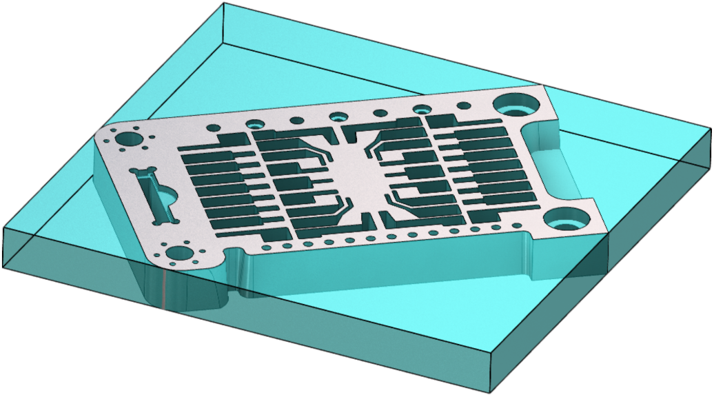
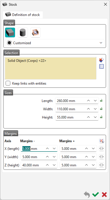
The next step enables to create/modify the shape, the size and the position of the stock. The default stock created is cubic, but you can choose a cylindric shape or a specific solid. By default, the stock is the bounding box of the solid with 5 mm more in the 6 directions X+, X-, Y+, Y-, Z+, Z-. You can modify this value of 5 mm, in the Margins. For the workflow, the default values are those preset in the previous workflow operation. For detailed information on the stock creation, click on the link here. |
|
|

|
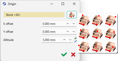
There are 2 possibilities for positioning of the origin:
After selecting the point, you can move it on the Z axis by defining an Altitude. By default, the origin is set at the maxi Z of part. An offset on X axis (DX) or Y axis (DY) can also be set according to the reference point. For additional information on the creation of program origins, click the link here. |
|
|

|
|
Toggle the Analyze step off (red) or on (green) to avoid or allow application of cycles computation. Mostly applicable for automatic validation of the workflow. |
|
|
|
|||
|
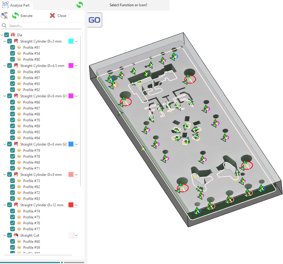
This step launches the Part analysis function. The various typologies of the part are analyzed and compatible strategies are automatically applied. If Color Analysis is activated in the ribbon, the colors of the faces are recognized and strategies defined with colors are applied. This is the final step and upon validation, the machining cycles will be automatically computed and the machined part will be presented. For details about the part analysis process, click the link here. |
|||