
Presentation
|
The Turning/Swiss/Vertical Lathe workflow starts by importing a file. Some ribbon icons and operation sequences are exclusive to this module. The current step appears highlighted in teal. The ribbon divides into three zones, as shown below. |
||

|
||
|
|
Dynamic ribbon: Provides all the steps to proceed with an imported part, up to the application of machining cycles. Some steps may or may not appear, for instance the identity step will only appear if the imported file contains multiple parts. The user can revert to a previous step anytime by clicking the ribbon icon and making necessary modifications. |
|
|
|
Environment: The zone to define the machine and material. This can be accessed and modified anytime in the workflow steps. |
|
|
|
Validation controls: |
|

|
Validation of the current step and proceed to the next step. Validating the final step completes the workflow wizard and finalizes the computation of the toolpaths. The same is achieved on validating (green tick) through the dialog for each step. |
|

|
Available as a drop down from the main validation button. It allows for automatic validation of default values (preset settings saved from previous workflow operation), quickly going through the steps and computing the machining toolpaths. |
|

|
This button stops and exits the workflow wizard at any point in the workflow steps. All prior setups done in the wizard are saved. |
|
|
Watch these video showing the workflow in action. |
||

|

|

|
Environment
|
This is usually the first setup that is carried out, even though it can be modified/updated at any moment in the workflow. This section lets you set up the machine and define the material at any workflow stage. It offers a complete programming process with part and machine setup through this ribbon. 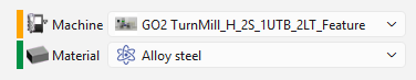
The drop-down lists for machine and material rely on the user database and compatibility. A color code appears left of each category, as follows: RED: Nothing is set or defined for the category YELLOW: Automatic preset based on previous settings. Data from the prior operation is saved GREEN: Manual selection completed. If a Machine or Material has been defined in the software configurations, these are always prioritized and automatically set in the workflow. The indicator is GREEN for this situation. |
The Dynamic Ribbon

|
The first step in the ribbon, launching the workflow on loading a part either through the GO button If a single part is in the imported file, a bounding box is generated to envelop the solid. At any point in the workflow process, the user can click on the Import icon to revert back and relaunch the import operation. |
|
|

|
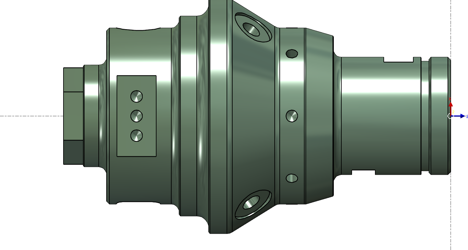
This step is only available if several CAD files are imported at the same time or the imported file contains multiple solid parts. It launches the dialog for the treatment of the list of solids. For more information about multiple solid imports and the dialog, click the link here. Recognition and distinction can be made between parts, stock, symbols and work-holding devices. |
|
|

|
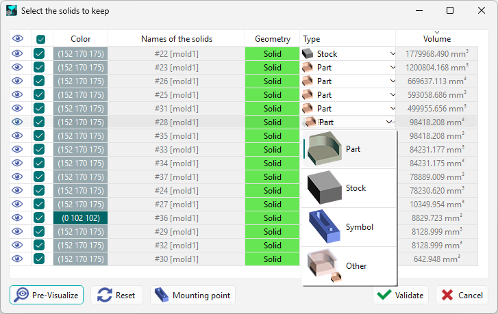
This step is the positioning of the solid and the stock along the Z axis of the Revolution plane. |
|
|
|
|
Click the face where the revolution axis is to be defined, then click the return the part button |
||
|
|
Optimize part positioning according to the axis, it will translate the origin to center the part as much as possible. |
||
|
|
You can also orient the workpiece by inserting the orientation angle. This will rotate the part along the Z axis. |
||
|
|
Select a face to orient the X axis |
||

|
|
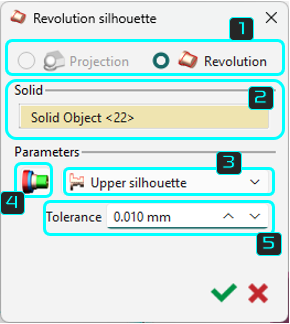
Select between Projection and Silhouette |

|
|
|
Select the solid object of which you want to create the silhouette |
||
|
|
There are three types of silhouettes to choose from: upper silhouette, lower silhouette, and symmetrical silhouette. |
||
|
|
Assigning color to silhouette elements If the solid file has faces in various colors, users can apply these colors to the silhouette during import by selecting the icon below (gray at first, colored when chosen) and confirming. This function is useful for automatic threading in an automatic opelist. The opelist window lets you pick a color for the silhouette to apply the threading cycle. |
||
|
|
Select the field Tolerance enables to modify the automatic calculation of the 2D silhouette by default it is 0.001 mm. |
||

|
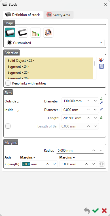
The next step enables to create/modify the shape, the size and the position of the stock. The default stock created is cylindric, but you can choose an N sides cylinder or a specific solid. By default, the stock is a cylinder with 5 mm radius around the part. You can modify this value of 5 mm, in the Margins. For the workflow, the default values are those preset in the previous workflow operation. For detailed information on the stock creation, click on the link here. |
|
|

|
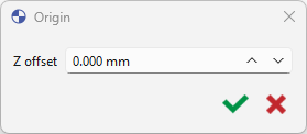
Enter a value or click any edge point to set the Z offset. For additional information on the creation of program origins, click the link here. |
|
|

|
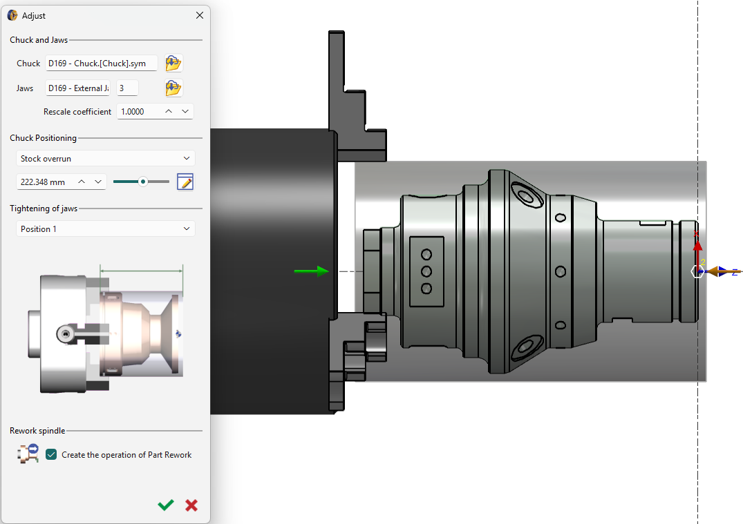
If a chuck is defined in the machine file, this step automatically adjusts the stock optimally. The user can still switch chuck and jaws and adjust the scale. This reduces the need for readjustments, but the dialog box remains available for manual settings. Details about the adjustment settings are available by clicking the link here. |
|
|

|
|
Toggle the Analyze step off (red) or on (green) to avoid or allow application of cycles computation. Mostly applicable for automatic validation of the workflow. |
|
|
|
|||
|
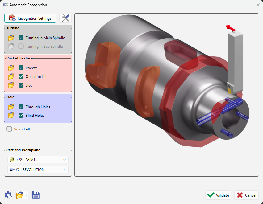
This step launches the automatic recognition of features on the solid for application of machining cycles based on features opelists. This is the final step and upon validation, the machining cycles will be automatically computed and the machined part will be presented. For details about the general machining features, click the link here. |
|||
