
Presentation
|
Launch the DXF workflow using the GO button The ribbon divides into three zones, as shown below. |
||

|
||
|
|
Dynamic ribbon: Guides through all steps for processing an imported DXF file, from positioning to cleaning. The user can, at any point in the workflow, revert back to a previous step by clicking on the ribbon icon and carry out modifications as required. |
|
|
|
Environment: This zone defines the machine and material. You can access and modify it anytime during workflow steps. |
|
|
|
Validation controls: |
|

|
Validation of the current step and proceed to the next step. Validating the final step completes the workflow wizard and finalizes the computation of the toolpaths. The same is achieved on validating (green tick) through the dialog for each step. |
|

|
Available as a drop down from the main validation button. It allows for automatic validation of default values (preset settings saved from previous workflow operation), quickly going through the steps and computing the machining toolpaths. |
|

|
This button stops and exits the workflow wizard at any point in the workflow steps. All prior setups done in the wizard are saved. |
|

|
Watch a video showing the workflow in action on importing a DXF file. |
|
Environment
|
This is usually the first setup that is carried out, even though it can be modified/updated at any moment in the workflow. This section allows to setup the machine and define the material for stock. It provides a complete workflow experience with a programing process with the part and machine setup, just through this ribbon. 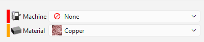
The drop down list for the machine and material is based on the user database and compatibility. A color code is associated on the left of each category. The representation of the color code are as per below: RED: Nothing is set or defined for the category YELLOW: Automatic preset based on previous settings. Data from the previous operation is saved GREEN: Manual selection has been done. If a Machine or Material has been defined in the software configurations, these are always prioritized and automatically set in the workflow. The indicator is GREEN for this situation. |
The Dynamic Ribbon

|
The first step in the ribbon, launching the workflow on loading a part either through the GO button or a drag and drop. This opens the CAD import dialog; for more details on that, click the link here.
At any point in the workflow process, the user can click on the Import icon to revert back and relaunch the import operation. |
|

|
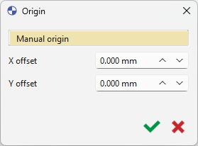
There are two options for positioning the origin:
The offset on X and Y axis is set according to the reference point. For additional information on the creation of program origins, click the link here. |
|

|
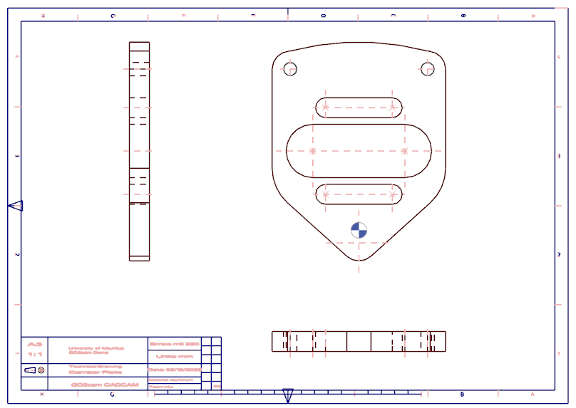
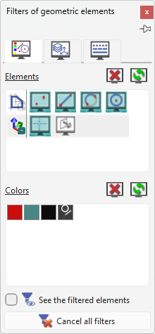
Upon importing and positioning your origin, utilize the toggling of layers, colors, and additional parameters during filtering to effectively isolate geometry and optimize the workspace environment. For detailed information regarding the filter dialog please refer to the following link.
|
|
|
Watch a video on using filters: 
|