
Presentation

|
This command facilitates the selection of a clamping element and its precise positioning on the current workpiece. Clamping elements include vices, clamps, and various support components. |
The elements may be defined within the environment designated as Clamping / Toolholders. Users have the capability to either design these elements or import solid models. For comprehensive details regarding this creation process, please refer to the following resource: Creation of Components.
|
Watch this video on the vice and clamps dialog: |

|
1. Import a Vice
|
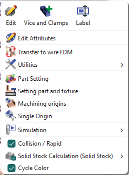
To import a vice and position it, please adhere to the following procedure: Within the Machining tree, right-click on the line labeled Stock and choose the option "Vice and Clamps". |
|
|
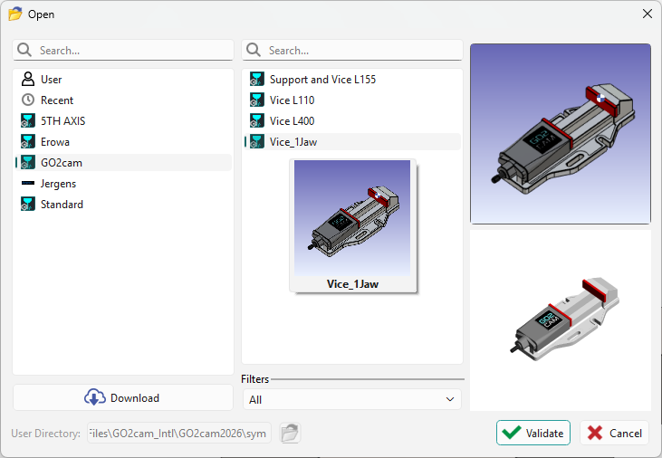
Select the vice from the list and perform validation. You may select the element from several available libraries:
|
|
|
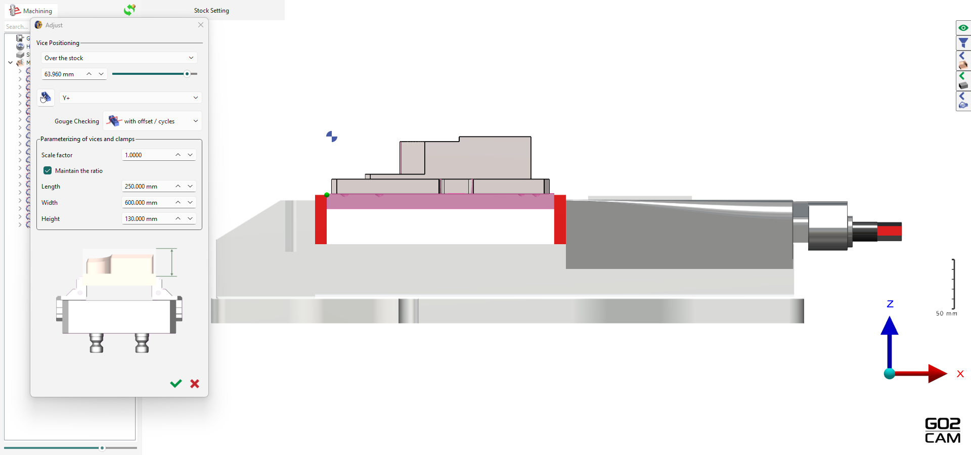
When you validate your vice, it automatically adjusts its position to the corresponding workpiece stock. You can manage the vice position through the dropdown, accessing:
You can also select the vice orientation along the X and Y axes. |
|
|
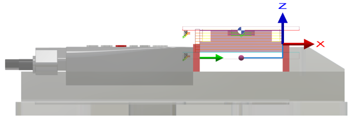
Adjust the vice by clicking the manual setting in the dialog Use the X, Y, Z axes or enter values in the corresponding fields to translate the vice. Click the “Green Tick” to validate. |
|
|
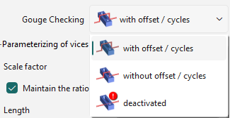
Define the Gouge Checking option to manage collisions for the vice. |
|
|
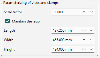
Adjust the vice parameters—length, width, and height. You can scale them simultaneously using the scale factor or adjust each separately by deactivating maintain the ratio |
|
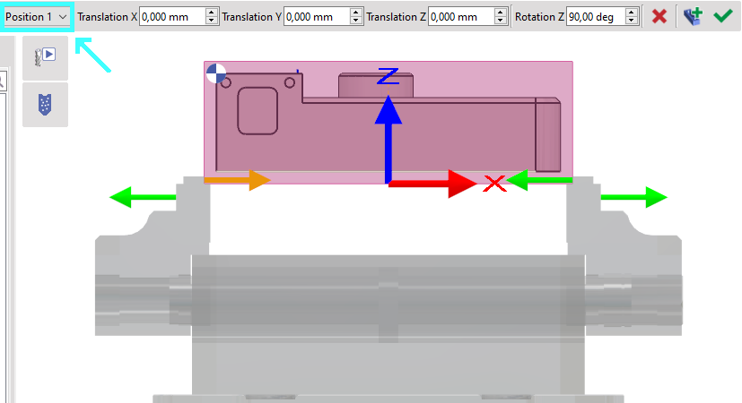
2. Case of a Vice with Multiple Tightening
Some vice have several possible positions of tightening the part. In that situation, a new field appears in the dialog area and enables to choose the position.
|
Here, Position 1 is selected. The part is too large and the jaws go out of their room. |
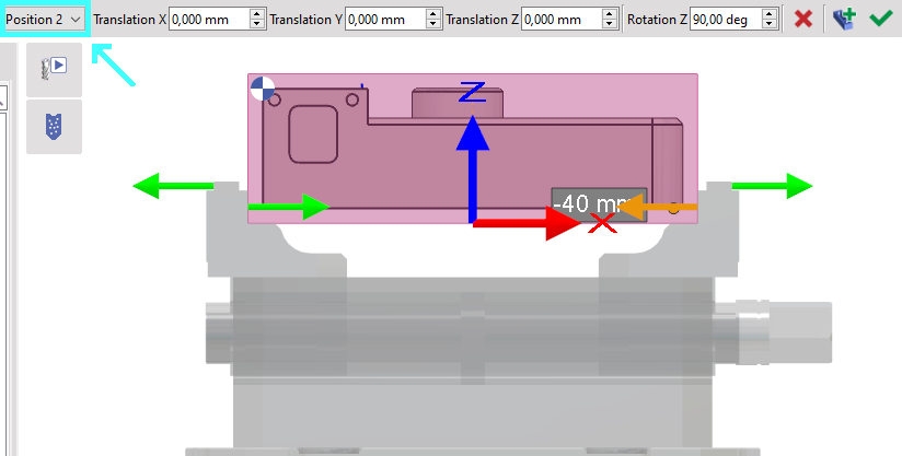
We switch to Position 2 and we can see that it is much better. Note that the position in Z is directly given by the system of axis defined during the vice creation. |
|
|
|
▶️ This video shows how to create a vise with Multi-tightening and how to use it on a solid.

|
3. Special Case: Flip-Flap of a part
|
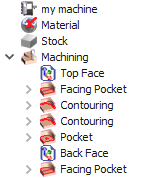
You will have to associate the vice to the part setting “Top Face” and “Back Face”. |
|
|
|
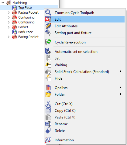
To align the vise with the Top face: Right-click on the “Top Face” and select Edit |
|
|
|
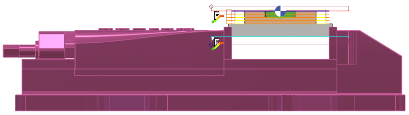
Select the symbol associated with the setting and choose the vice. Double-click on the "Green Tick" to confirm the selection and proceed with validation. Click on "Update" followed by "Total." |
|
|
|
|
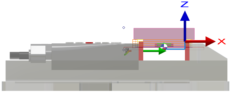
Change the Plane from ‘Reference’ to ‘Back Face’ |
|
|
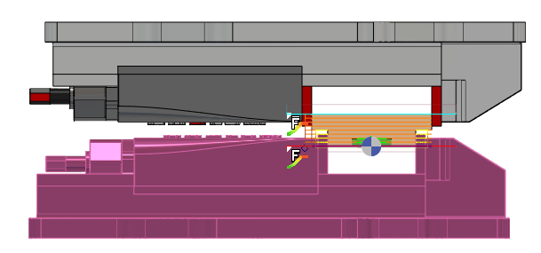
Repeat the procedure to install the vice and ensure it is precisely aligned with the rear face of the workpiece. |
|
|
|
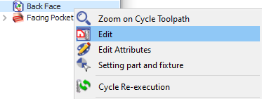
To associate the vice to the Back face: Right click on the “Back Face” and Edit |
|
|
|
Select the symbol associated with the setting and choose the appropriate option. Double-click the green tick to confirm your selection and validate the choice. Proceed by clicking on Update and then Total. |
|
|
|
▶️ You can watch a video on Vice Setting for Top Face and Back Face:

|