
1 General Information
|
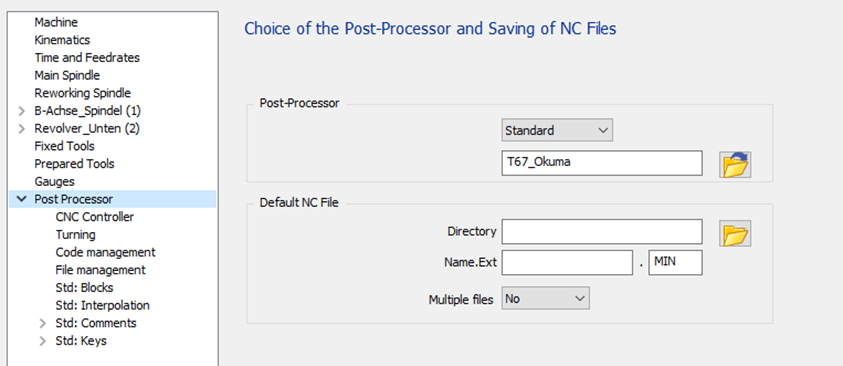
The standard has four configuration pages to manage all options available :
|
|
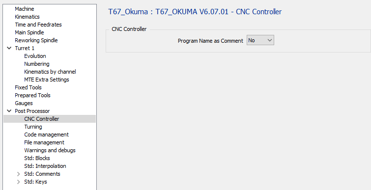
2 CNC Controller page
|
2.1 CNC Controller - Program Name as comment
|
Option |
Result |
|
No |
… … M30 % |
|
Yes |
(PART NAME) … … M30 % |
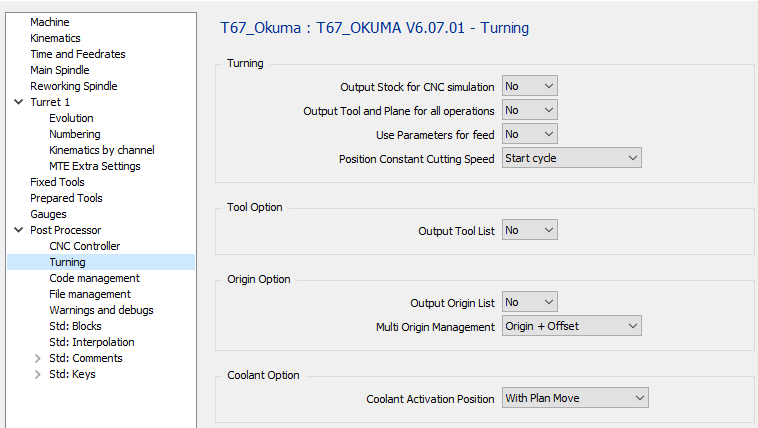
3 Turning page
|
3.1 Turning – Output Stock for CNC Simulation
No stock output for T67_Okuma standard post-processor.
|
Option |
Result |
|
No |
T0101 … … |
|
Yes |
T0101 … … |
3.2 Turning – Output Tool and Plane for all operations
|
Option |
Result |
|
No |
O1000 (FACE) TD=010001 M323 G00 X20 Z2 … … (ROUGH) G00 X20 Z2 … … |
|
Yes |
O1000 (FACE) TD=010001 M323 G00 X20 Z2 … … (ROUGH) TD=010001 M323 G00 X20 Z2 … … |
3.3 Turning – Use Parameters for Feed
|
Option |
Result |
|
No |
… TD=010001 M323 G00 X20 Z2 G01 Z-20 G95 F0.1 … … |
|
Yes |
VSET F1 = 0.1 TD=010001 M323 G00 X20 Z2 G01 Z-20 G95 F=F1 … … |
3.4 Turning – Position Constant Cutting Speed
|
Option |
Result |
|
Start cycle |
TD=010001 M323 G50 S9000 G110 G96 S40 M04 G00 G90 X44.8 Z2.4 … |
|
Start machining |
TD=010001 M323 G97 S284 M04 G00 G90 X44.8 Z2.4 G50 S9000 G110 G96 S40 M04 G42 G01 G95 Z0. F0.1 … |
3.5 Tool Option – Output Tool List
|
Option |
Result |
|
No |
… TD=010001 M323 … … |
|
Yes |
… (START TOOL LIST) (T1 CMNG 04) (T2 ...) (T3 ...) (END TOOL LIST) TD=010001 M323 … … |
3.6 Origin Option – Output Origin List
No output for T67_Okuma standard
3.7 Origin Option – Multi Origin Management
No change for the standard T67_Okuma. No multi-origin management on Okuma.
|
Option |
Result |
|
Origin Only |
… |
|
Origin + Offset |
… |
With B axis machine :
The origin offset is outputted with the tilted plane function G127 with the G code G174.
3.8 Coolant Option – Coolant Activation Position
The second and third option will give the same output for turning operation.
There will be a difference by milling operations using livetools.
|
Option |
Turning operation |
Milling operation (livetool) |
|
With Spindle |
… TD=010001 M323 S1000 M03 M08 G00 X15 Z2 … |
… TD=010001 M323 S1000 M03 M08 G00 X15 C0 Z2 … |
|
With Plane Move |
… TD=010001 M323 S1000 M03 G00 X15 Z2 M08 … |
… TD=010001 M323 S1000 M03 G00 X15 C0 M08 Z2 … |
|
With Plunge Move |
… TD=010001 M323 S1000 M03 G00 X15 Z2 M08 … |
… TD=010001 M323 S1000 M03 G00 X15. C0 Z2 M08 … |
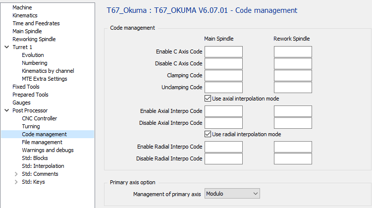
4 Code management page
|
4.1 Code Management – Enable C Axis Code
If the field is empty, the default code is M110.
|
Option |
Result |
|
“empty” |
… TD=010001 M323 S1000 M03 G17 M110 G28 G90 H0 C10 … |
|
M51 |
… TD=010001 M323 S1000 M03 G17 M51 G28 G90 H0 C10 … |
4.2 Code Management – Disable C Axis Code
If the field is empty, the default code is M109.
|
Option |
Result |
|
“empty” |
… X200 M109 M09 … |
|
M50 |
… X200 M50 M09 … |
4.3 Code Management – Clamping Code
If the field is empty, the default code is M147.
|
Option |
Result |
|
“empty” |
… C10 M147 G01 Z-10 … |
|
M10 |
… C10 M10 G01 Z-10 … |
4.4 Code Management – Unclamping Code
If the field is empty, the default code is M146.
|
Option |
Result |
|
“empty” |
… G00 Z20 M146 C10 … |
|
M11 |
… G0 Z20 M11 C10 … |
4.5 Code Management – Use axial interpolation mode
If machine don’t have code to output axial interpolation,it can be done in decomposed.
No circular interpolation will be output don’t use tool offset
|
Option |
Result |

|
Output axial operation with interpolation |

|
Output axial operation decomposed |
4.6 Code Management – Enable Axial Interpo Code
|
Option |
Result |
|
“empty” |
… G01 Z-5 … |
|
G112 |
… G01 Z-5 G112 … |
4.7 Code Management – Disable Axial Interpo Code
|
Option |
Result |
|
“empty” |
… G00 Z20 … |
|
G112 |
… G113 G00 Z20 … |
4.8 Code Management – Use radial interpolation mode
If machine don’t have code option to use interpolation, it can be done in decomposed.
No circular interpolation will be output don’t use tool offset
|
Option |
Result |

|
Output axial operation with interpolation |

|
Output axial operation decomposed |
4.9 Code Management – Enable Radial Interpo Code
|
Option |
Result |
|
“empty” |
… … |
|
G107 |
… G107 … |
4.10 Code Management – Disable Radial Interpo Code
|
Option |
Result |
|
“empty” |
… … |
|
G107 |
… G107 C0 … |
4.11 Primary axis option – Management of primary axis
|
Option |
Result |
|
Modulo |
… C0 … C359 C0 … |
|
Linear |
… C0 … C359 C360 … |
|
Incremental |
Not manage by machine. Modulo will be used |
5 File management page
|
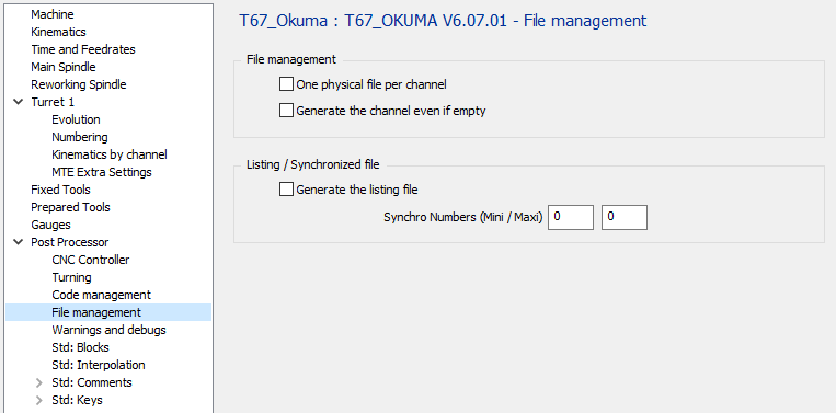
5.1 File Management – One physical File per Channel
|
Option |
File 1 |
File 2 |

|
(FIRST CHANNEL PROGRAM) … … M30
(SECOND CHANNEL PROGRAMM) … … M30 |
|

|
(FIRST CHANNEL PROGRAM) … … M30 |
(SECOND CHANNEL PROGRAMM) … … M30 |
5.2 File Management – Generate the channel even if empty
|
Option |
Result |
|
|
If a channel is empty no output of the program |
|
|
If a channel is empty, the program will be output but empty (Just O1001 and M30 will be output) |
5.3 Listing / Synchronized File – Generate the Listing File
You need to set the Synchro Number mini & maxi to output the listing
|
Option |
Result |
|
|
Don’t generate the file to see the synchro between channels. |
|
|
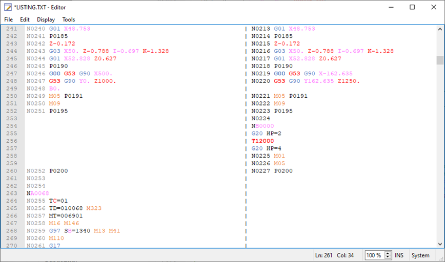
Generate the file to see the synchro between channels. |
The file with the name Listing.TXT will be temporarily generated and shown.
|
5.4 Listing / Synchronized File – Synchro Numbers (Mini / Maxi)
Define here the synchronization Numbers (for example 1 – 9000)
The post processor will search for the synchronizations numbers between these mini and maxi values to generate the Listing.TXT file.
6 Launch page
|
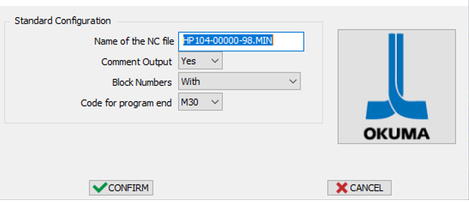
6.1 Name of the NC File
Define here the Name of the generated NC file.
The extension is defined in the MCF configuration.
6.2 Comment Output
|
Option |
Result |
|
No |
… … TD=010001 M323 … … |
|
Yes |
… … (FACING) (CNMG 04) T0101 … … |
6.3 Block Numbers
|
Option |
Result |
|
With |
N0001 TD=010001 M323 N0002 G00 X10 Z20 N0003 Z10 … … N0010 TD=010002 M323 N0011 G00 X20 Z20 N0012 Z10 … … |
|
Without |
TD=010001 M323 G00 X10 Z20 Z10 … … TD=010002 M323 G00 X20 Z20 Z10 … … |
|
Tool Change Only |
N0001 TD=010001 M323 G00 X10 Z20 Z10 … … N0002 TD=010002 M323 G00 X20 Z20 Z10 … … |
6.4 Code for Program End
|
Option |
Result |
|
M30 |
… … … M30 |
|
M02 |
… … … M02 |
7 Specific informations
7.1 MTE movement from the machine origin
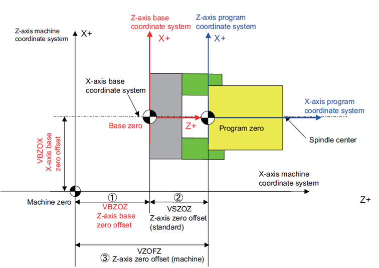
Because the points are given in the system of axis of the machine, if there is 2 turrets not at 180 degrees, you have to recompute the X value to output a correct value in the turret axis system.
On Okuma machine there is no using of program origin. We have to program with using machine variable to be able to program fixed point from the machine origin.
We have to cancel the tool offset too.
To program a Z position relative to the machine zero without tool offset, we have to program the following lines :
Z=[<Z position to reach> - VZOFZ – VZSHZ - VETFZ]
X=ABS[<X position to reach> - VZOFX – VZSHX- VETFX]
VZSHZ is the current shifting added to the active offset.
VETFZ is the current active tool offset in Z axis.
|