
Introduction
Managing turning tools in MTE is much more complex than milling ones due to the various options and positions possible for tool mounting in turnmill and Swiss machines. The processes for mounting and setting turning tools in MTE are detailed below.
Process for Tools with no prior Toolholders
Generally, it is advised not to set up toolholders for turning tools during the programming process.
The processes in MTE to load the tools in the machine are described below:
Inserting Holders
|
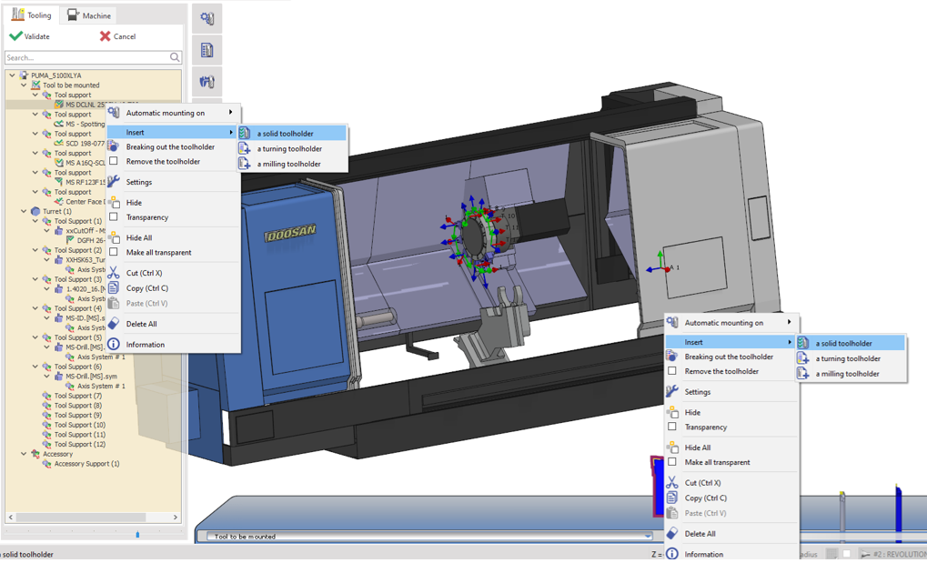
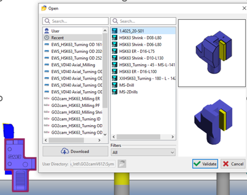
1/ Individual insertion Right-click on the tool in the tree or the tool rack and in insert, we can select a standard or solid toolholder to add to that tool. Repeat for each of the tools to add their respective toolholders. |
|
|
|
2/ Fixed tooling (Toolholder FMO) In the case where there is an FMO file with toolholders already preloaded, simply load the file to mount the holders in their respective positions on the turrets/racks. At this point you can individually mount the tools to the toolholders or use the automounting function. |
|
|
|
This video demonstrates the different ways to manage toolholders in GO2cam, including inserting, copying, applying, and replacing holders directly from the tool rack using right-click menus. Watch to see these flexible options in action and learn how to efficiently organize your tool setup. 
|
Tool mounting methods
There are multiple ways to manually mount tools in MTE. A specific Auto Mounting function is also provided to automate the full mounting process. The mounting methods are detailed below:
-
Using the Drag & Drop in the Tooling Tree
|
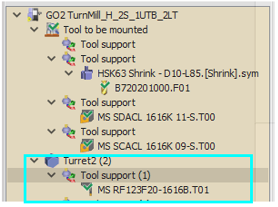
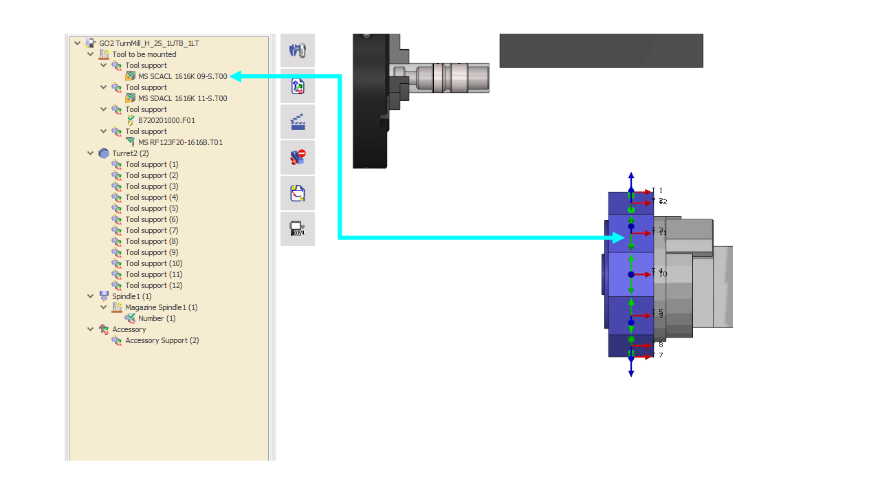
In the tooling menu, you’ll find a section labeled ‘Tool to be Mounted’. Each tool support in this section contains a tool that needs to be mounted. To manually mount a tool, simply drag and drop it from the ‘Tool to be Mounted’ section to an available tool support on your turret or spindle. Example:
|
|
|
|
-
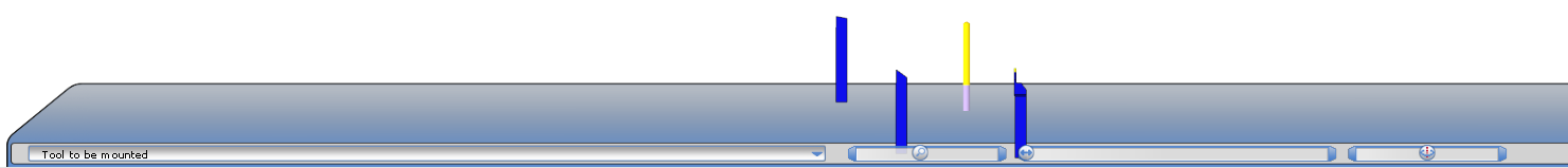
Drag & Drop of 3D tool from Rack to Turret/Spindle
|
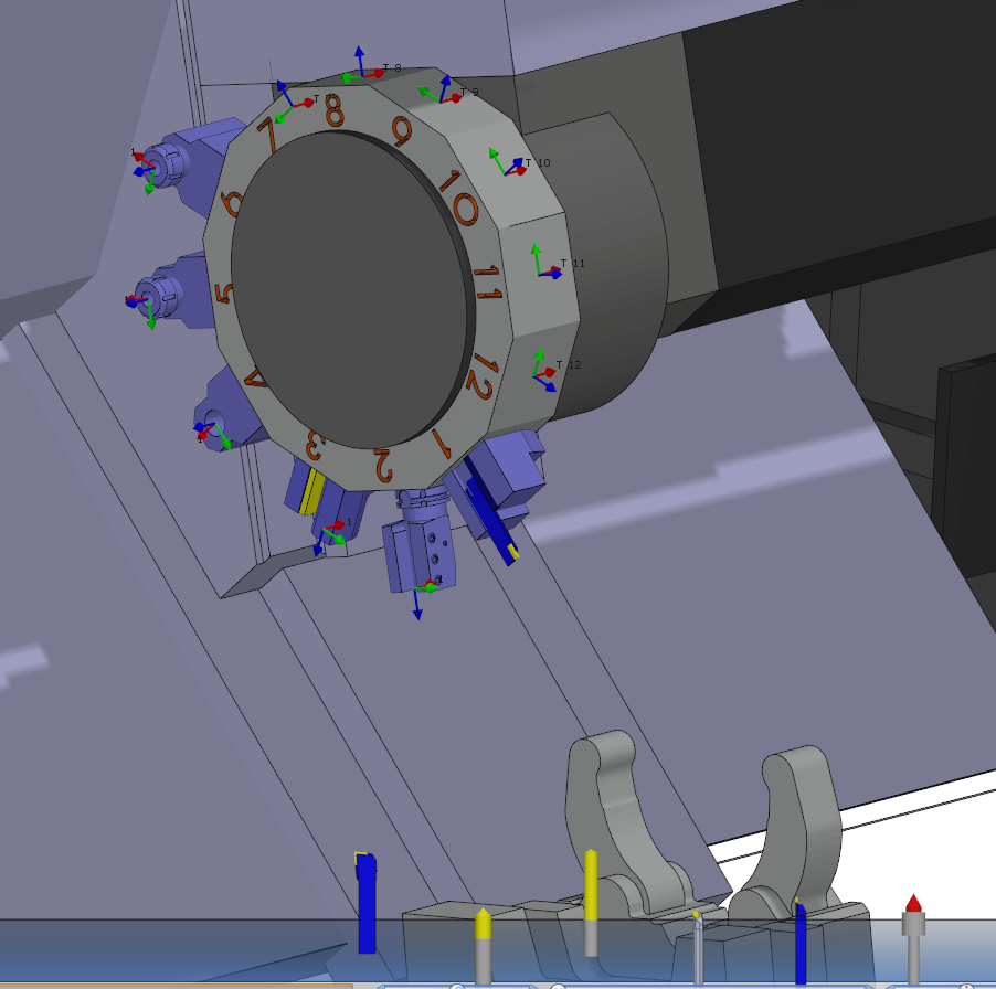
In the MTE Tooling Interface, you’ll find a rack at the bottom(shown in Image 3) containing tools ready for mounting. To manually mount a tool, simply drag and drop the 3D model onto the desired turret or spindle tool support, each of which is labeled with a numbered axis system for easy identification. |
|
-
Drag & Drop from Tooling Tree to Turret/spindle.
|
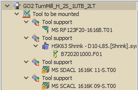
In the "Tool to be mounted" section (shown in Image 1), you can mount tools by dragging them directly to your turret or spindle. The mounting process is simple:
|
|
|
Here you can watch a video demonstrating the different methods of performing manual tool mounting on an MTE machine. |
|
-
Auto Mounting
|
This function automates the process of mounting each tool to their respective toolholders on the turrets/racks with just a couple of clicks. The software does the optimization and positioning of the tools based on some rules and prior setups. This is advantageous to improve process repeatability and shortens the tool mounting process significantly to just a few seconds! More details about the Auto Mounting function can be found in the dedicated page here. |
|
|
The Assign Tools of Machine command allows users to quickly replace placeholder tools with the actual mounted tools from the FMO file by right-clicking on the machine or the Tool to be mounted section. The compatible tools are automatically mounted. After the replacement, the mounting process can be finalized as usual.
|

|
Process for Tools with Toolholders
Users may also prefer to work with toolholders attached with the tools during the programming process.
In MTE, the user can directly mount the tool/toolholder pair to their required positions either manually or with auto mounting.
Changing the Toolholder
In the case where the initially mounted toolholder is not appropriate, the user has the possibility to change or replace it with another.
When the toolholder is inserted during the programming process, in MTE the tool/toolholder setup is considered as a single entity. GO2cam provides some functions, as described below, which allow manipulations of the toolholder.
|
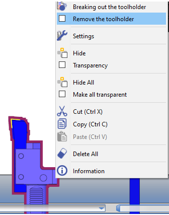
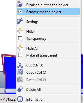
Remove the toolholder With the tool/toolholder as a single entity, activating this function(checks the box) removes the toolholder while still conserving its history. If the function is deactivated, the tool is reverted back to its initial tool/toolholder setup.
|
|
|
|
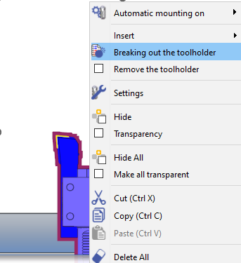
Breaking out the toolholder This function separates the tool and the toolholder into 2 separate entities. The user can delete the toolholder and insert another one or simply change the toolholder with the Replacing the toolholder command. If the toolholder is deleted, the Remove the toolholder function is automatically activated. |
|
|
|
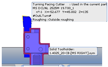
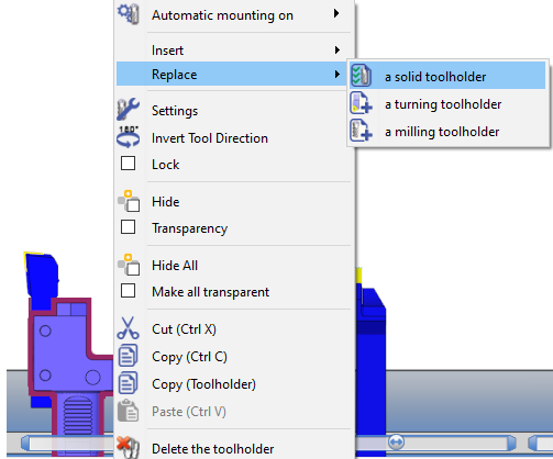
Replacing the toolholder If the user right-clicks on the current toolholder (separate entity), the Replace command can be used to change to another solid or standard toolholder. If the replaced toolholder is deleted, the Remove the toolholder function is automatically activated. On deactivating the function, the tool is reverted back to its initial tool/toolholder setup as a single entity. |
|
|
Quickly move and position tool holders in GO2cam’s Tooling Menu using drag-and-drop and pop-up options, then compare your tool setup to the workpiece with the indexing feature.

Specific Case: Tool indexing on a turret with multiple indexing position per station
|
This case is explained with an example: Turret with 12 stations and 24 indexing positions To manage the dual tools indexing on such a turret, define the indexing angle in the toolholder definition.
|

|