
Auto Mounting in Milling
|
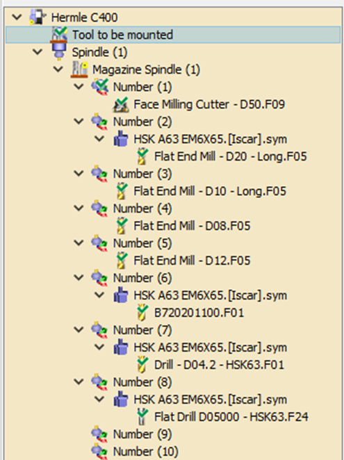
This function is designed to streamline and automate the entire process of mounting each tool to its corresponding support within the Magazine Spindle. The functionality ensures that all tools located on the tool rack, which are designated to be mounted, will seamlessly transition to the magazine spindle. Each tool will be assigned a specific number, facilitating easy identification and organization. For more information on Auto Mounting, click here.
Milling toolholders must be attach to the tool before entering the MTE module, as this offers multiple benefits. For more information, visit help Tool Page. |
|
|
The Assign Tools of Machine command allows users to quickly replace placeholder tools with the actual mounted tools from the FMO file by right-clicking on the machine or the Tool to be mounted section. The compatible tools are automatically mounted. After the replacement, the mounting process can be finalized as usual.
|

|
|
|
A new field has been added in the machine numbering settings to allow you to start automatic tool numbering from a specified position. This enables you to reserve free positions in the magazine. |

|
Manual Mounting
|
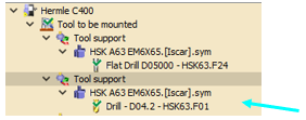
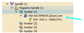
Using the Drag & Drop in the Tooling Tree In the tooling menu, find the section labeled ‘Tool to be Mounted’. Each entry in this section contains a tool that needs mounting. To manually mount a tool, drag and drop it from the ‘Tool to be Mounted’ section to an available tool support in your Magazine Spindle. Example:
|
|
|
|
Managing the Toolholder
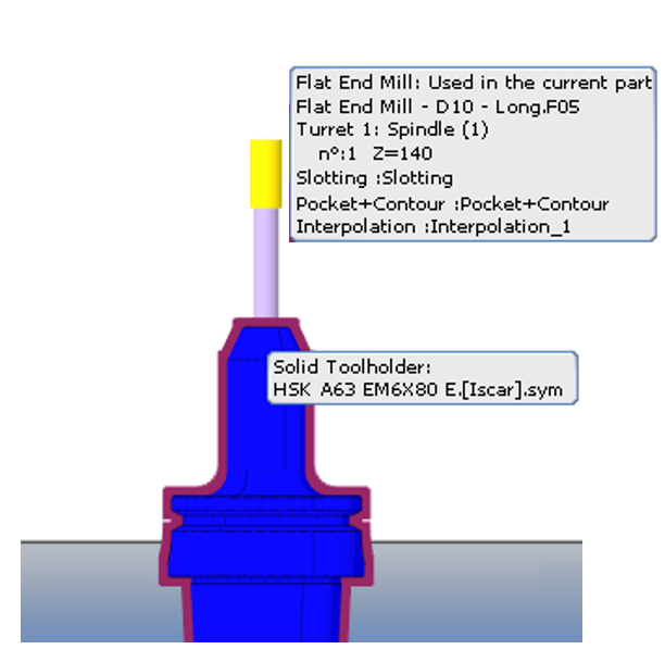
When the toolholder is inserted during the programming process, in MTE Tooling it is considered as a single entity. GO2cam provides some functions, as described below, which allow manipulations of the toolholder and the tool.
|
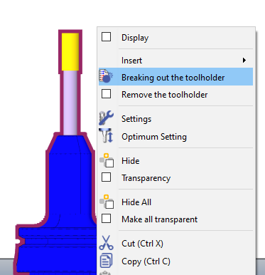
Breaking out the toolholder This function that lets you separate a combined tool and its toolholder into two distinct, manageable entity. By separating them:
|
|
|
|
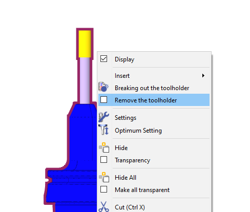
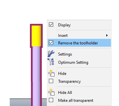
Remove the toolholder With the tool/toolholder as a single entity, activating this function(checks the box) removes the toolholder while still conserving its history. If the function is deactivated, the tool is reverted back to its initial tool/toolholder setup.
|
|
|
|
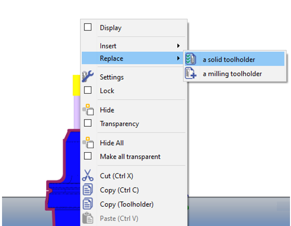
Replacing the toolholder If the user right-clicks on the current toolholder (a separate entity), they can use the Replace command to switch to another solid or standard toolholder.
If you delete the replaced toolholder, the Remove the toolholder function activates automatically. Deactivating it reverts the tool to its original setup as a single entity. |
|
|

|
||
Fixed tools
In MTE Milling, you can use the Fixed Tools function to pre-load tool setups from a saved .FMO file. These files store specific tool and toolholder characteristics, like length and diameter, for later use. A key advantage of FMO files is their machine-independent nature, allowing you to use the same tooling configuration across multiple machines.
Loading and Updating FMO Files
To use an FMO file, you must first load it into your machine file. This is done by editing the machine, navigating to the Kinematics tab, and selecting the desired .FMO file.
A crucial setting within the machine file is Systematic Update:
-
NO: The .FMO file will not change, even if you modify the tooling in the menu.
-
YES: The .FMO file will automatically update to reflect any changes made to the tooling setup, ensuring it always matches the current state of the machine.
In cases where no holder has been mounted prior to the MTE, you can insert a toolholder before doing the auto mounting or manual mounting.