
This page refers to the robot strategy dialog in version 6.12.207.
Recall :
The toolpath of the cycle is calculated beforehand. For each point of the toolpath, the following data is provided:
-
Point location
-
Z-axis orientation (X and Y axes remain undefined)
Differences Between 6-Axis Industrial Robots and Traditional NC Machines
-
Redundant configurations:
2 for shoulder, 2 for elbow, and 2 for wrist → total of 8 possible configurations. -
Redundant turns (especially on J4 and J6):
The same Cartesian path can be executed with J6 entering [-180°, 180°] or [180°, 540°]. -
Redundant orientations of the TCP (tool center point):
6-axis industrial robots provide a fully defined tool orientation. If the X and Y axes are not defined beforehand, the possible orientations are infinite.
Need for a Reference Position
To convert a toolpath with partially undefined orientation into robot joint positions without ambiguity, a reference position is required. From it we extract:
-
Robot reference configuration (kept throughout the cycle).
-
Robot reference joint angles, to which the first generated robot position will be fitted (to determine joint turns, especially J4 and J6).
-
Reference TCP orientation, used to define the lead-in tool orientation.
The reference position can be defined as:
-
Joint format (robot-specific) → tool orientation via forward kinematics,
-
Cartesian format with configuration (generic) → joint positions via inverse kinematics.
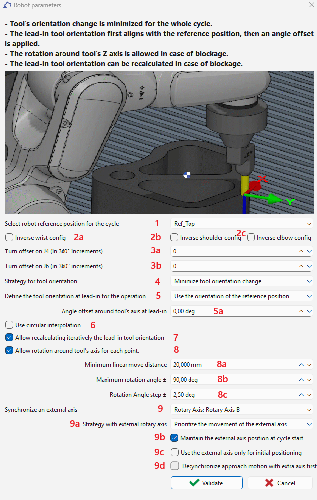
Robot Reference Position (1)
For a cycle containing multiple sub-cycles (e.g., drilling several holes within a single cycle), the reference position is applied only to the first sub-cycle. For all subsequent sub-cycles, the robot’s last joint position is used as the reference.
The reference position can be selected. By default, the robot’s position prior to the cycle is used. This reference position is used for :
-
Define the shoulder-elbow-wrist configuration, maintained throughout the cycle (can be inverted by options 2a, 2b, 2c).
For a cycle containing multiple sub-cycles (e.g., drilling several holes within a single cycle), the configuration inversion is applied only to the first sub-cycle.
-
Define a reference joint angle position, used so the first generated joint position is as close as possible to it. This avoids ambiguities in axes with multiple turns (commonly J4 and J6, sometimes endless). Further turn adjustments can be applied with 3a and 3b.
For a cycle containing multiple sub-cycles (e.g., drilling several holes within a single cycle), the turn offset of J4 or J6 is applied only to the first sub-cycle.
-
Propose a reference TCP orientation (in case of a carried tool). The lead-in tool orientation can then be:
-
aligned to this reference orientation and rotated by an offset angle (5a), or
-
aligned to the tangent of the toolpath with a fixed offset angle (5b), depending on option 5.
-
Tool Orientation Management (4)
-
Two modes are available:
-
Minimize tool orientation change for axis-symmetric tools
-
The orientation is kept as stable as possible.
-
If necessary, this rule can be overridden when option 8 is enabled.
-
-
Follow toolpath tangent with offset For non-axis-symmetric tools such as a blade
-
The Following toolpath tangent with offset mode is not applicable to drilling-type cycles (drilling, tapping, and threading), as the tangent is undefined.
-
If a continuous move (linear or circular) fails due to reachability, joint limits, or singularities, then in Minimize orientation change mode, with option 8 enabled, the TCP can be rotated around its Z-axis to make the path feasible.
-
Drawback: This may cause large rotations over small distances, leading to undesirable effects (e.g., over-cutting in deburring). Options 8a and 8b help prevent this.
-
-
For approach, retract, or return points (where the tool is not in contact with the part), rotation is always allowed in both modes.
External Axes (9)
An additional external axis can be defined:
-
Linear axis moving the robot, can be synchronized with robot joint axis.
-
Rotary axis moving the part, can be synchronized with robot joint axis.
-
Linear axis attached to the robot flange, moving the tool along the TCP’s Z-axis, selectable only for drilling, tapping or threading cycles. This axis cannot be synchronized with robot joint axis).

The axis must have a non-zero identifier to be available for selection in this dialog and to synchronize with the robot axes.
In the case of external axis synchronization, additional options 9a, 9b and 9c are available.
9a — Synchronization Strategy with the 7th Axis
You can select the synchronization strategy between the robot and the 7th axis:
-
Prioritize 7th-axis motion:
The 7th axis movement is prioritized in order to keep the robot as close as possible to the longitudinal position defined by the selected reference position relative to the external axis. -
Minimize tool orientation change:
The system minimizes variations in the tool orientation (Z-axis of the tool frame, as defined by the reference) during synchronized motion.
9b — Lead-In Position Strategy
You can choose how the system reaches the lead-in reference position:
-
Robot-only approach:
The robot moves to the reference position while the external axis remains stationary. -
Synchronized approach:
Both the robot and the external axis move simultaneously to reach the selected reference position.
9c — Path Execution Mode
You can define whether the subsequent path is executed:
-
By both the robot and the external axis, allowing synchronized motion, or
-
By the robot only, with the external axis remaining fixed during path execution. In this mode, the external axis is used solely for approach positioning and does not participate in the coordinated motion during the path..
9d — If desynchronize approach motion
If a collision occurs during simultaneous robot and external axis motion at the first approach point, this option can be used to enforce sequential motion: the external axis moves first, followed by the robot, to avoid the collision.
Additional Options
-
2a, 2b, 2c: Invert shoulder, elbow, or wrist configuration.
-
3a, 3b: Apply a turn offset to J4 or J6.
-
Example: If J6 is limited to [-720°, 720°] and its value before the cycle is 680° (near the upper limit), applying a turn offset of -1 changes the reference J6 to 320° (680° – 360°).
-
-
5: Select method for lead-in orientation offset.
The Defining an offset from toolpath tangent method is not applicable to drilling-type cycles (drilling, tapping, and threading), as the tangent is undefined.
For a cycle containing multiple sub-cycles (e.g., drilling several holes within a single cycle), the angle offset is applied only to the first sub-cycle. For all subsequent sub-cycles, the robot’s last joint position is used as the reference and the offset will not be applied.
-
6: Activate circular interpolation.
-
7: If the cycle fails, GO2robot searches iteratively for a valid lead-in orientation, using an angle step defined in 8c. If successful, value 5a or 5b is updated with the new parameter.
The search for a valid lead-in orientation is not applicable to cycles containing multiple sub-cycles (e.g., drilling several holes within a single cycle).
-
8: enable tool orientation change in mode Minimize tool orientation change. 8a, 8b: Additional constraints to avoid excessive orientation changes.
Frequent or excessive orientation changes over short distances may lead to undesirable robot motion behavior, such as overall speed reduction, vibration, or loss of path accuracy. Therefore, it is recommended to apply Option 7 (search for lead-in orientation) before enabling this option.