
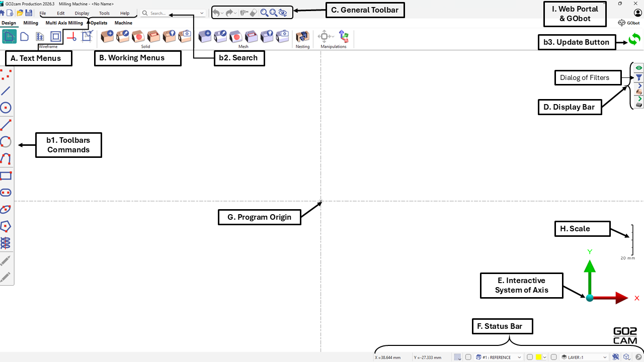
The GO2cam user interface comprises menus, toolbars, and working bars. The following sections provide detailed explanations of these components.
A. Text menus: Located at the top of the screen, these menus grant access to the software's general commands.
B. Working menus: situated below, these tabs and menus enable access to GO2cam’s commands organized by task (Design(wireframe &solid), Milling, Turning, Multi Axis Milling, Opelists and Machine etc..).
b1. Toolbar of commands: positioned on the left, this contextual toolbar displays commands that vary according to the selected working menu. The blue arrow provides access to less frequent but complementary commands.
b2. Search: facilitates rapid location of any GO2cam element, including geometry, machining operations, tools, planes, layers, attributes, or text. Users may apply filters and combine criteria such as name, type, color, tool, or layer to identify relevant items, which can then be selected, edited, or toggled for visibility within the graphic area.
b3. Update Button: This button updates geometry and machining cycles following modifications. When changes impact machining cycles (such as operation relocations, tool substitutions, or parameter adjustments), GO2cam displays an orange balloon indicating that an update is required. Activating the Update function recalculates machining processes accordingly. Note that changes affecting only geometry do not trigger this notification.
C. General Toolbar: Icons are located at the top of the GO2cam environments and include common commands such as eraser and undo, as well as graphic tools like framing and zoom.
D. Display Bar: This right sidebar features a filter dialog at the top, enabling users to conceal elements by type, color, and additional criteria. The remaining icons provide quick access to visibility and transparency settings for primary elements including the part, stock, symbols (such as vice and clamps), and tools.
|
E. Interactive System of Axis: This feature provides a visualization of the current plane axis and offers access to various views, enhancing user interaction and spatial orientation.
F. Status Bar: An interactive interface element displaying cursor coordinates, grid dialog, coordinate system definitions, plane and layer management, current color settings, and geometric element visualization.
G. Program origin: Denotes the 0,0,0 coordinate location for the current plane. Upon launching GO2cam, this serves as the reference plane in Milling and Wire EDM modules and as the revolution plane in Turning operations.
H. Scale: Represents the approximate dimensions of a workpiece, component, or toolholder. The scale dynamically adjusts in response to zoom operations.
I. Web Portal & GObot: The Web Portal is the main gateway to GO2cam online services like downloads, updates, tools, databases, docs, and support. It also links to services like GO2support, news, and videos. The GObot is an AI assistant in GO2cam and the Portal that answers questions, suggests help pages, and runs JavaScript API commands via chat.
|
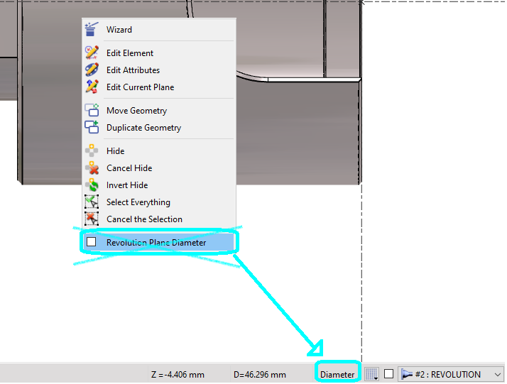
In the Turning design interface, the selection between Diameter and Radius coordinate systems has been relocated from the popup menu to the status bar, where it is now implemented as a toggle switch. The active mode is displayed prominently in the status bar, ensuring that this information remains visible on the screen at all times. |
|