Presentation
|
|
|
The Status Bar is the interactive strip at the bottom of the GO2cam window that centralizes graphic and design controls such as coordinates and grid, workplane, active color, layers, attributes, solid edge display, and the information window. |
Coordinates and Grid steps
|
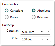
Access grid options directly from the status bar. The status bar dialog provides direct access to grid settings and design coordinate definitions (cartesian or polar, absolute or relative). It replaces previous background popups, enhancing grid visibility. You can call it with the Ctrl key while designing geometry or performing other actions. |
|
|
|
|
The new Grid Display adapts the grid step to your zoom level and highlights every fifth line. This provides a clear, scale-aware reference, making distances and orientation easier to read at a glance. Watch the video below for a demonstration. |
|

|
||
For Turning, the choice between Diameter and Radius coordinates moved from the popup menu to a switch button in the status bar; the current mode always displays there, so you can see which coordinate mode is active.
List of Planes
The list of planes appears in the Status Bar. Select a plane to set it as the current workplane.
The checkbox on the left filters elements belonging to the current plane.
Right-click to access commands:
|
|
Recover a plane |
Click an element to display its plane number and select it as the current plane. |
|
|
Edit current plane |
Modify the current plane by renaming, deleting, or changing creation characteristics (angles, origin coordinates, etc.). You cannot modify the REFERENCE plane. |
|
|
Rename |
A new plane receives an automatic number and name. You can rename it later. |
|
|
Delete current plane |
You can delete the current plane unless it contains elements or you created another plane from it. You cannot delete the REFERENCE plane. |
|
|
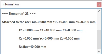
Information |
Displays the plane name, type, and coordinates relative to the REFERENCE plane. |
Active Color
|
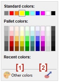
The active color appears in the status bar and is no longer managed in the top pallet. GO2cam offers an infinite pallet based on RGB mode (Red/Green/Blue). Click the color icon to open the dialog box shown on the right:
The checkbox on the left filters and shows only elements with the current color. |
|
|---|
List of Layers
You can quickly access the list of active layers and select the current layer. The list and table of layers are available by right-click. You can also rename a layer and select the current layer by entering its number.
The checkbox on the left enables filtering elements to show only those in the current layer. For more information on layers, click here.
|
|
Recover a layer |
Click an element to display its layer number and select it as the current layer. |
|
|
Choose a layer |
Open the layer list to modify the current layer. |
|
|
Rename |
Name the current layer. |
|
|
Manage the layers |
Open the layers table to customize layer files (*.LAY), assign names, and more. |
|
|
Copy current layer in… |
Copy all contents of a layer to another. Select the current layer, click the command, and enter the duplicate layer number. |
|
|
Enter a number |
Select a layer by its number. |
Attributes
|
|
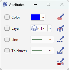
Management of Attributes |
The current attributes are defined in the palette: color, line type, line thickness, and layer number. This command allows filtering elements by attribute type, such as displaying only red elements. You can also recover existing attributes by clicking an element with the pipette. Multiple selection is possible through a reorganized and improved dialog box. |
|
|
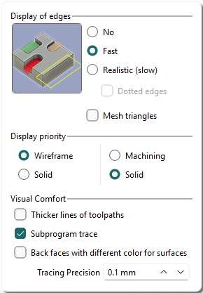
Display of solid edges
Use the dialog box to configure edge display and set the display priority for 2D, 3D, and machining operations.
|
|
|
|
|
|
|
|
|
|
For large parts, use the Fast/Solid/Solid combination for faster processing: save up to 25% time, improve motions, and prioritize the solid display for clearer part understanding.
Information window
When a message appears, the dialog closes after 10 seconds with a fade, but messages are retained. Description of the behavior:
|
|
Inactive |
There is no message. |
|
|
Updated |
There is a new message, click the button to read it. |
|
|
Hide |
The dialog is open. Click the button to hide it, and keep the messages. |
|
|
Active |
The dialog is closed, but messages are available. Click the button to open it again. |
Closing the window with the red icon deletes the message and returns the information icon to an inactive state.