
These menus enable to access the general commands of the software. Here are some detailed explanations of the whole list of available commands.
File
Management of files, import of CAD files and printing options.

|
New |
Creation of a new part. |
||||

|
Open |
Open a file already saved. Shortcut: Ctrl key +O. |
||||

|
Save |
Save the current file. Shortcut: Ctrl key + S. |
||||

|
Save As... |
Save a file for the first time, or duplicate the file by giving it a new name. |
||||
|
More information about Save, backup and Open files are available. |
||||||

|
Automatic Solid Import |
In Milling and Wire-cut EDM: import of a solid file, positioning by clicking the support face and automatic creation of the stock. Click here for more details. |
||||

|
Automatic Solid Import |
In Turning only: import of a solid file, automatic positioning according to its revolution axis and automatic creation of the 2D silhouette. Click here for more details. |
||||

|
Import |
Loading a file from a CAD software. The list of CAD interfaces and the process to treat them is explained here. |
||||

|
Export |
The current file can be exported and saved in a CAD format. Most of the standard exchange formats are supported: 2D as DXF and DWG, 3D as PDF, IGS, SAT, X_T, STL and STEP and also images formats such as JPEG, BMP and PNG. For Parasolid .X_T files, the option to enter the version of the file to save is also available in the preview window. The version is entered in a window dialog. |
||||

|
go2transfer secured |
go2transfer is a service of data files transfer for professionals looking for security and confidentiality. In order to meet the safety requirements, we have designed an innovative and robust system. It is offered to GO2cam end-users. Click here for more information. |
||||

|
Add… |
|
The main function of the commands is to add a GO2cam File or a CAD file on the current PCE file. Click here for more information. |
|||
|
|

|
GO2cam File |
While working with a PCE file, you can add another PCE file on the current one. The main purpose is to add geometry or import a stock shape. Behaviour:
|
|||
|
|

|
CAD File |
While working with a PCE file, you can add a CAD file on it. This is opened with the CAD standard interfaces. There is no automatic positioning, you will have to do it once the part is imported. |
|||
|
|

|
Assignment of solids |
This enables to access to the table of assignment of solids, where you decide whether a solid is the workpiece, the stock, a clamping element or something else. |
|||

|
Importing Tools… |
In Forming tools/Tools Libraries modules only: this option enables to import tool data stored under GTC format, which is an international standard for tool data exchange. More information, click here: Importing Tools - GTC Standards. |
||||

|
Save Temporary File |
Safety saving of the current job, even if the file is not saved. |
||||

|
Recover Temporary File |
Recovery of the latest saves of the current job. You have the ability to define automatic savings every x actions. Define this number x in the Software Configuration of GO2cam (click GO2cam logo in the homepage), then page ‘Save’. |
||||

|
Print Preview |
Preview of the page to be printed. |
||||

|
|
Adjustment of printing options (scale, frame, etc.) and launching of the printing. |
||||

|
Working Directory |
Ability to force the addressing of several directories into 1 only directory:
The [name] of the folder is displayed in the menu The command Project / Reset enables to restore standard addressing. |
||||

|
Project |
|
Submenu for the management of projects. A project is a set of files: part file (*.PCE), machine files, used tools, material file, symbols, etc. The projects are especially very useful for technical support. |
|||
|
|

|
Reset |
Ability to reset all the addressing of folders that are done when loading a project file. It is necessary to do it before selecting a new project. |
|||
|
|

|
Select |
Selection of a project that had already been opened, located in the folder Trans. |
|||
|
|

|
Import |
Load of a new project. The different folders and files included are saved into the folder Trans. You can also import a project by drag and drop in GO2cam main window. |
|||
|
|

|
Export |
Save the current part with all the relative data (machine, tools, symbols, post-processor, etc.) into a project file. |
|||

|
Recent Files |
|
List of the files recently opened in the software, with the ability to display up to 10 files. |
|||
|
|
Back to the Homepage |
To change the environment. |
||||

Edit
Modification of elements, filters and selection.

|
Undo |
Cancellation of the last actions done. This command allows multiple use. Click here for more details. |
||

|
Redo |
Command linked to the Undo command. Click here for more details. |
||

|
Select All |
Selection of all the elements visible on the screen. |
||

|
Undo Selection |
Cancellation of the current selection. |
||
|
Extra information about the selection of entities are given here: The selection in GO2cam |
||||

|
Hide |
Ability to hide one or several elements. Right-Click in the background to choose this option. You can watch a video (double-click in the video to enlarge it!) |
|
|

|
Invert Hide |
After hiding some elements, you can invert the command. |
||

|
Cancel Hide |
The elements hidden are visible again. |
||

|
Cancel all Filters |
Cancellation of all the filters defined on the part (hide command, filters etc). |
||

|
Edit Element |
Modification of the position and topology of the selected element. Display: edited element is shown in purple (color Alternative2), the elements created after the edited element are grey, the elements linked with edited element in white. We invite you to read 2 different pages regarding specific elements: |
||

|
Recreate Element |
This command is now independent, it is not anymore included in Edit Element, which becomes more simple. When you do a right-click on an element and choose Recreate, you are back in the command to create again this element. It is only available on wireframe elements. |
||

|
Edit Attributes |
Modification of the attributes of the selected element: the color, the line type and thickness, the layer. The current attributes are defined in the command Management of Attributes : :Palette: Edit Attributes and Management of Attributes have a similar and easy behavior. |
||


|
Move Geometry Duplicate Geometry |
These commands can be used to move/duplicate any type of geometry:
Click here for much more details. |
||

|
Change Plane |
This command helps to change the workplane of wireframe or solid elements. More information: click here! |
||

|
Cut Geometry |
Those 3 commands enable to cut or copy any types of geometric elements and paste them on another position. The keyboard shortcuts Ctrl+X, Ctrl+C and Ctrl+V can be used. Click here for more information. |
||

|
Copy Geometry |
|||

|
Paste Geometry |
|||

|
Database |
|
||
|
|

|
Delete Element History |
When a geometrical element is created in GO2cam, the history of creation is kept in database, to enable parameterizing of design. The parameterizing is a powerful functionality of GO2cam. In some cases, the history is not correctly defined and may generate troubles for design. In this case, you can delete the element history |
|
|
|

|
Retrieve Erased Ref Elements |
You can give a name to a geometrical element thanks to the command Info Entity in the menu Help. If this element has been deleted later, you can recover it thanks to this command, by giving the name of the element or by the name given to the element by the system. For more information about this command, click here. |
|
|
|

|
Part Update |
When you work on CAD files with dataGO, you can update the model if modifications have been done in the CAD software. The modifications will be taken into account in the current GO2cam part, even if machining cycles have already been programmed. With dataGO, you can also read holes features. The dialog box has completely been renewed. |
|
|
|

|
Holes Models Update |
For FTE files only: if you modify a hole model which has already been used and positioned in the part, you can do this update to apply the modifications to the elements in position. The plugin to export FTE files from the CAD software is not provided anymore. But compatibility is ensured: you can still import *.FTE files in GO2cam. To replace FTE process:
|
|
|
|

|
If symbols have been modified in the Components environments, you can update them to take into account these modifications in the current part. |
||
|
|

|
Tools Update |
If you modify a tool which is defined as fixed or prepared in the machine, you can update the database to take the modifications into account in the machine. |
|
|
|

|
Machine Update |
In the current file, ability to update the *.MCB machine file that had been previously modified. It is the same command as the one in the machine file, the access is more rapid here. |
|
|
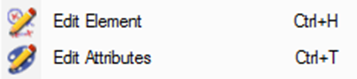
Keyboards shortcuts are available for most of the commands. They are pointed out directly in the menu, at the end of line. For instance, the commands Edit Element and Edit Attributes are 2 of the most used commands in GO2cam, you will use them very often to modify the characteristics of the element. Their shortcuts are: Ctrl + H and Ctrl + T. |
|
Standard shortcut for left-hand users are available:
-
Undo: Alt+Back Space
-
Redo: Ctrl+Shift+Z
-
Cut: Shift+Del
-
Copy: Ctrl+Ins
-
Paste: Shift+Insert
Display
Zoom on details, display options and 3D rotation.

|
Display dotted lines |
With this option, you activate the display of dotted lines on the solid. For this, the ‘Display of edges’ in the status bar is automatically set to ‘Realistic’ mode. Read more about this command: click here. |

|
Display priority to the solid or wireframe/machining |
If selected, the command gives display priority to the solid compared to other geometric elements and machining operations. These options are also available in the status bar, command ‘Display options’. |
|
|
Tools visibility |
Hiding tools has now 3 status: Full tool visible, Tool only visible (holder hidden), Full tool hidden. This command can be added to the Customize Menu. (For more info, watch a video on this option: Click here) This happens only during selection of geometry while defining machining cycles. |

|
Dynamic Rotation |
Activate the dynamic rotation with the mouse: you can move your part in 3 dimensions by maintaining the left button of the mouse. When the part is positioned as you wish, type the Enter key to block the view on this position. |

|
Zoom + |
Zoom forward by scale (x2). |
|
|
Zoom |
Zoom by window, to see details of part file. |
|
|
Zoom - |
Zoom backward by scale (/2). |

|
Framing |
Automatic positioning in a view extending the visualization to all the elements of the drawing. |

|
List of Views |
Access to the whole list of views. Click here for more details. |

|
Changing Views |
Access to Isometric, Front And Above views. |

|
User Views |
The User Views enable to create 3 customized views (zoom scale and position). Click here for more details. |


Tools
Launching of external applications and macros and customization commands.

|
Calculator |
Access to a standard calculator. |
||

|
Editor |
Access to a text editor, by default it is the GO2cam NC editor. You can choose another editor, define it in Tools>Options>Customization. Click here for more details. This editor has improved options: powerful syntax coloring, management of multi windows for channels, search improved, etc. |
||

|
Visual Keyboard |
This tool is an accessibility utility that displays a virtual keyboard on the computer screen. This keyboard allows people with physical impairments to type data by using a pointing device, a joystick or a mouse. Another functionality of the keyboard is the ability to manage different languages, this is especially useful for the accented letters in languages such as French, Spanish, or German as well as for Russian and Greek. |
||
|
|
Standard Macros |
Special commands such as engraving, creation of text on circle, creation of table of points, formula etc. |
||

|
Specific Macros |
Here you can find the macros developed especially for the customer by the reseller or the editor. |
||
|
|

|
JavaScript is a modern, easy to use, and easy to learn scripting language. GO2cam provides a Javascript API to write scripts and improve automation of your process. This API allows to:
Click on the API Help for more information. |
||

|
Reading Points File |
Ability to read files of points with any file format extension, with choice of separator and the result that we want to generate (points, polygon or curve) You can watch a video on Reading Points File (double-click in the video to enlarge it!): |
|
|

|
Customize Menus |
Creation of customized text menus, more information are given in the previous page. Read the help page: Customize Menus. |
||

|
Customize Toolbar |
For expert users, creation of toolbar with your favorite commands. You can create a different toolbar for each environment (CAD Interfaces, Milling, EDM etc.). Read the help page: Customize Toolbar. |
||

|
Customize List of Operations |
Creation of a user machining list. The machining list displays the cycles programmed on your part and is available in the machining tree, in the machining commands. |
||

|
Import from Another Version |
|
New in V6.11: ability to recover users data from previous version, such as files of configurations, tools, tec files, symbols etc. Please click here for more information: Import from Another Version. |
|

|
Options |
Access to many options of the software: customization of the graphic user interface, units and tolerances, display preferences and general options for machining. Many details are given here: Software Configuration. |
||


Opelists
Creation, modification of opelists and update of menu. A page is dedicated to this topic: Opelists Manager

|
Create |
Creation of an opelist by inserting the operations one by one. |

|
Create / GO2cam File |
Creation of an opelist from a GO2cam file (PCE) The purpose is to read the list of operations of an already machined part and to save this list as an opelist. |

|
Modify |
Modification of an existing opelist. |

|
Tools Update |
When a tool is modified in GO2cam, you can apply the modification in the opelist(s) that you select. |

|
Total Tools Update |
When a tool is modified in GO2cam, you can apply the modification in all the opelists |

|
Machine Grade Update |
You can define a machine grade and apply it to one or several opelists selected in the explorer. No need to edit the opelist(s) to modify it (them). |

|
Material Grade Update |
You can define a material grade and apply it to one or several opelists selected in the explorer. No need to edit the opelist(s) to modify it (them). |

|
Update Menus |
After the creation or copy of opelists, you can update the menus of selections in GO2cam. |
|
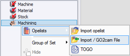
As explained in the previous table, GO2cam is able to create an opelist from an already machined PCE file. There is another similar command, available in the Machining Tree, in Machining/Opelist: Import / GO2cam File The purpose is to apply an opelist in the current part by reading an already machined PCE file. |
|
Help
Documentation, downloading of data and information about the file and the software.
|
|
Web Portal |

|
The web portal offers a unique access to all the websites and services provided by GO2cam International. More information : click here. Download Libraries are also available in the web portal. |
||

|
Online Help |

|
You can enter GO2cam online help this way, or press F1 while beginning a command or on the machining dialogs. |
||

|
Update Software |
Update of GO2cam by downloading patches. |
|||

|
Remote Support |
If you get in contact with your local reseller for Technical Support, you can click this command to give the ability to technician to remote your GO2cam. There is nothing necessary to install. We use a license of TeamViewer12. |
|||

|
Element Info |
Click any element (geometry, cycle...) to get information about it. You can also give a name to geometrical elements. |
|||

|
File Info |
The general characteristics of the part file are given here. |
|||

|
About |
Information about GO2cam: version, User ID, copyrights, third parties etc. The information regarding Solid CAD interfaces and the license are now available in this command: |
|||

|
Interfaces |
List of the solid CAD importers available in GO2cam. The importers which are not available with the current license are noticed with the term ‘not allowed’. The list of 2D interfaces is also given. The full list is given here: List of CAD interfaces |
|||
|
|
Options |
List of products and options available with your license. |
|||

|
License |
Display of customer license agreement |
|||

|
Qt 6.5.3 |
Information about Qt, a C++ toolkit used by R&D for GO2cam development. |
|||

GO2cam Operator
Menu dedicated to the configuration and use of the software GO2cam Operator.

|
Traceability of the project |
This command enables to compare the files of a same project together, to determine the differences between the part programmed originally in GO2cam and the part modified in GO2operator. The information and the knowledge are recovered from the machine shop to the methods department, ensuring this way the traceability of the project. |

|
Customization of editing |
This command enables to create users who can have different kinds of rights in GO2operator. |
|
|
Online Help |
Explanation about the software GO2cam operator. |