
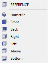
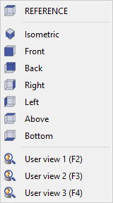
A view represents a position from which the part is observed. The default views provided are relative to the Reference plane: REFERENCE denotes the Top view, followed by the Isometric (3D) view, as well as the Front and Side views. Upon creation of a workplane, a corresponding view is automatically generated bearing the same name, representing the Top view of that plane.
List of views
|
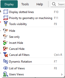
There are multiple methods to access the list of views:
A shortcut key F8 is also available for quick access. |
|
Shortcuts
|
Access to the various views is also available via keyboard shortcuts.
Please note that these shortcuts are functional exclusively with the numerical keypad keys. Activation requires pressing F7 to toggle the shortcut mode on or off, followed by the corresponding numerical key to switch to the desired view. Utilization of any other command will automatically deactivate the shortcut mode, necessitating pressing F7 again to reactivate it. |
|
F7 + 1 |
Face view |
You can watch a video demonstrating these shortcuts:
|
|
F7 + 2 |
Bottom view |
|
|
F7 + 3 |
Inverted ISO view |
|
|
F7 + 4 |
Left view |
|
|
F7 + 5 |
Isometric view |
|
|
F7 + 6 |
Right view |
|
|
F7 + 7 |
Back view |
|
|
F7 + 8 |
Reference view |
|
|
F7 + 0 |
Switch from a view to the next one |
|
|
V |
inversion of the current view |
You can watch a video demonstrating the inversion key: 
|
PAN/Translation and Rotation of Views
|
To move or rotate a workpiece across the screen, you may toggle the action by either pressing the F7 key or by pressing the scroll button on your mouse. The pointer will change to a hand symbol, after which you can perform the following actions:
|
You can watch a video showing the PAN/Translate in action:
|
The users views
Notes:
-
Users views are now saved by product (not anymore in the PCE file). They appear in the List of views.
-
The users views can be used in dynamic simulation.
|
Create customized views. To establish a customized view, position the desired section on the screen according to your preference, adjusting the zoom scale as required. Subsequently, press the keys Ctrl and F2 simultaneously. The view thus created can be accessed by pressing the F2 key or via the list of views, where it is designated as User view 1 (F2). It is possible to create up to three views by utilizing the Ctrl key in combination with the F2, F3, and F4 keys. |
|
▶️ You can watch a video demonstrating the creation and usage of user views:

|
|
▶️ You can watch a video on Users Views, Tools Visibility, Customize menu & Shortcut for Visibility options: 
|