
|
|
List of new features and Improvements of GO2cam V6.11.201, released on 1st of March, 2024. Improvements added all along version’s life: Improvements of Revisions |
|
Icons used in the tables below |
|
New Features |
|
Improvements |
|
|
Web and Services
|
|
|
|
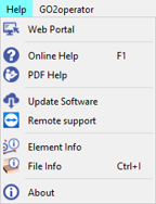
The user can create an account and then will be able to accede to several services with only one portal:
This portal also provides interesting information and news about GO2cam. Location: Help>Web Portal It has been introduced in GO2cam V6.10.206, in july 2023. |
|
|
|
go2transfer is a service of Data Files Transfer for GO2cam End-Users. Location: File>go2transfer secured It has been introduced in GO2cam V6.10.206, in july 2023. |
|
|
|
Installation, System & Hardware
|
||
|
|
System |
Executable files from GO2cam (*.exe files) now have a valid digital signature. This signature ensures the authenticity and integrity of the executable file. It prevents firewalls from blocking their installation. |
|
|
|
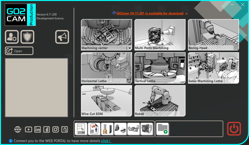
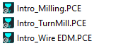
Ability to recover users data from previous version, such as files of configurations, tools, tec files, symbols etc. Location: Tools>Import from another version |
|
|
|
|
Now in GO2cam , user will be inform of new update by a message:
|
|
|
|
|
Hardware |
Management of DPI (Dots Per Inch) In Windows display settings, you can modify the size of Text, applis, etc. to 125, 150 % etc. This modification is now perfectly managed in all GO2cam dialogues. |
|
|
|
Open parts |
Compatibility : Opening a .PCE file lower than V5.8 (2008) is impossible. |
|
|
|
Application Programming Interface (API)
|
||
|
|
The GO2cam API has been completely renewed, by changing the language programming from Pascal to Javascript. A new Help for API has also been written: GO2cam Javascript API |
||
|
|
Many New Features are included in the API:
|

|
|
|
|
New Editor You can write the script directly in GO2cam by running this new editor. You can also get a preview of your program and validate your result on the scene. Location: menu Tools |
||
|
|
New standard macro: Part Family This allows to define a list of parts having similar features but with slightly varying dimensions so as to reduce the time required to program the machining of each part. The video on the right gives an overview of the macro. Another video is available in the API Help page demonstrating how to create a part family configuration. |

|
|
|
|
In GO2cam V6.10, the Standard Macros provided during many years have been removed from the software. We have re-written most of those programs in the Javascript language; they are available again. |
||
|
|
Graphic User Interface
|
||
|
|
4. Engaging Banner alerting you to the availability of the Latest Updates. |
|
|
|
|
Graphic Chart |
New GO2cam Logo for:
|
|
|
|
Now the user can tweak transparency with precision using the dynamic slider at the bottom of the machine tree, no more ON/OFF option. |
||
|
|
Working menu |
The working menu tab can now accommodate more menus (>6):
|
|
|
|
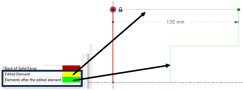
Two new colors of entities have been added. Edited element: the element that is being edited changes to the set color. Elements after the edited elements: all the elements that come after the element being edited change to the set color. |
|
|
|
|
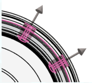
The color of the vectors of holes is managed and can now be customized in Theme by the color for Alternative 1. This allows the user to adjust the color for better viewing, based on their personalised theme. |
||
|
|
Color can now be added to back faces for surfaces to easily distinguish them. Color Customization can be done in Tools>Options>Theme> in the entity Back of solid Faces. |
|
|
|
|
New unit for duration created to differentiate with time unit:
Also enables to have same unit but different precision! Duration can be defined in seconds or milliseconds. |

|
|
|
|
New JavaScript Editor has been added under Tools menu. This API allows to write scripts and improve automation of your process. |
||
|
|
There are several improvements to the customize toolbars option:
|
|
|
|
|
|
|
|
|
|
Geometry Generalities
|
||
|
|
If we want to move a solid into a plane, and that the chosen plane was created on a face of the same solid, we forbid this action. The plane is not displayed in the list of possible destination planes. |
||
|
|
The Move axis system to axis system is a new command that help the user to move any geometry in any define axis set by the user. |

|
|
|
|
Interface for the Text dialog window has been updated with new icons and with added new features such as:
|

|
|
|
|
Wireframe Geometry
|
||
|
|
For wireframe geometry: when we edit an element, its color and the color of the elements built after it, can be customized in the Theme page of Tools>options. For more information, check the new feature for Theme. |
||
|
|
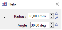
Angle option has been added for the Polygon and Helix commands, allowing to define the starting angle of the element. |
|
|
|
|
A Midpoint mode of creation has been added in the Point command. This provides the ability to create points at the exact mid-distance of 2 points; that can be extremities, centers or points. |
|
|
|
|
Wire-Cut EDM Geometry
|
||
|
|
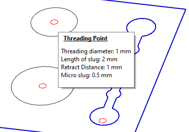
Threading Point |
When you create Threading points, the information are not anymore displayed in the screen. The information are now given into a balloon while passing the mouse over the threading point.
|
|
|
|
Workplanes
|
||
|
|
|

|
|
|
|
CAD Interfaces
|
||
|
|
Solid Import with Interop: Importing native files now enables to read the Holes Features from the following CAD systems:
|
||
|
|
SolidWorks Interface |
Ability to load SolidWorks configurations. It is possible to load several config at the same time (for instance 1 config that includes the part and another config that includes the stock). |
|
|
|
Dxf/Dwg Import: Our log report highlights the count of circles with unique centers. For instance, if a file includes 20 circles, but only 14 distinct centers, it indicates there are 14 distinct holes within the part. |
||
|
|
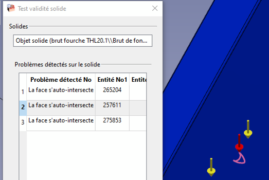
The import process has been revamped:
|
|
|
|
|
|
Ability to assign colours during automatic solid import in turning to the silhouette elements based on the solid colours.
|

|
|
|
|
|
|
|
|
New function in the PMI to run the measure between 2 solid faces to modify the value. This only works for annotations of distances and diameters. |
||
|
|
Types of PMIs are added in ‘Part Info’ The detail of number of PMIs by type is given: Nb Dimensions (semantics) / Nb Dimensions (graphics) /
Editing dimension does work only with Dimensions (semantics) |
||
|
|
New import : Rhino CAD software. The file format is *.3DM. Import of 2D elements and solids. |
||
|
|
Holes Features
|
|||
|
|
Creation of Users Holes Models |
|
New command: Users Holes Management This new command enables to enter in library of Users Holes and also to accede to the Creation of new models. |
|
|
|
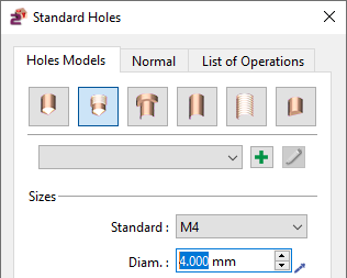
New Dialog window has been created with the same parameters as in the former versions. The parameters are organized differently, in 3 different tabs
|
|
||
|
|
In the new dialogs, we added a tab called Normal. It enables to define the normal direction of the holes. You can give the vector direction in X, Y and Z axis. By default, the position is X0 Y0 Z1, to be positioned in the Z direction of Reference plane. The pipette enables to pick a solid face to recover the direction automatically. |

|
||
|
|
Implementation of new standard holes dialog. We also added 2 improvements:
|
|||
|
|
Implementation of new standard holes dialog. Also, preview of the hole is now dynamic on the screen. |
|||
|
|
When recognizing through holes, the default direction of the recognized hole has been improved. |
|||
|
|
The color of the vectors of holes is managed and can now be customized in Theme by the color for Alternative 1. This allows the user to adjust the color for better viewing, based on their personalized theme. |
|
||
|
|
Machining Features
|
||
|
|
Milling Features |
Recognition of Pockets can now separate open and closed stages hence creating separate features for each. |

|
|
|
Milling Features |
In Recognition window, you now have the possibility to choose a library of hole models (standard or user). Recognition will then assign the first compatible model found in the selected library to the recognized holes. Note: This is only application if HMF package is present. |
|
|
|
Milling Features |
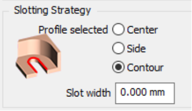
Machining of slots:
|
|
|
|
Milling Features |
Optimization in the order of machining has been improved when ‘Group Identical Features’ is activated:
|
|
|
|
Milling Features |
Minimum distance calculation (RGMF_SHORTED_DISTANCE): Calculation of minimum distance is not limited to only distance between pocket and island, or between 2 distinct islands. Now we are also able to determine the narrowest area of a pocket. (See video - General Enhancement) |
|
|
|
Milling Features |
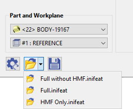
Save configuration files: In the automatic recognition window, you can load/save config files, which contain the types of features to search for, as well as the associated opelists. These files (.inifeat extension) are saved in the GO2cam Ini directory. (See video - General Enhancement) |
|
|
|
|
New command to create groove, in Shaft Creation:
|
|
|
|
Milling Features in Turning |
Millturn recognition differs from milling operations by identifying features across multiple planes.
In the turning module, you need an active Milling bit license. Otherwise, certain functions will be unavailable. The dialog box resembles the Milling one, but without facing, trimming (silhouette), or deburring options. However, it now includes the turning operations. |

|
|
|
Milling Features in Turning |
Machining areas of the part can sometimes be done either axially or radially (e.g., an N-pan around the axis of revolution).
For the moment, the axial case is chosen by default. There is still an option to be added in the dialog box. (See video - Features in MillTurn) |
|
|
|
Milling Features in Turning |
Millturn recognition extends to identifying features in a developed plane, based on revolution faces rather than planar faces.
(See video - Features in MillTurn) |
|
|
|
Milling Features in Turning |
Launch an automatic turning OPL based on recognized parameters, adapting to main or secondary spindle as per plane selection (revolution or rework/return plane). Grayed out if cycle exists in machining tree.
|
|
|
|
Machining Generalities
|
||
|
|
The creation of Stock has been completely renewed! Many new Features and improvements are available; we introduce them into 3 videos presenting 3 different situations:
|
|
|
|
|||

|
|||
|
|
New process to define origins. To homogenize the mechanism with MTE module, we added the table Machining Origins, in the Machining Tree, Line Stock. It is especially useful when you need several origins in your project.
Consequently, we cancelled the possibility to define an origin for an operation in the Machining Tree, Operation > Toolpath Techno. |

|
|
|
|
Toolpath and Dynamic Simulations The name of origin is now given in the table of coordinates. |
||
|
|
|
|
|
|
|
Copy tool across multiple cycles simultaneously. You now have the capability to replace one tool with another within a defined set of cycles, as long as all cycles are within the same folder. There are two approaches to achieve this:
|

|
|
|
|
Drag & Drop Previously, the option to use drag & drop was restricted to the creation of a new cycle in the geometry selection process. Now, it is also available when editing an existing cycle. |

|
|
|
|
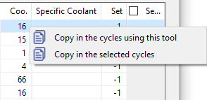
Coolant number in list of operations New ability to copy a coolant number:
|
|
|
|
|
List of Operations We added new field in the list of operations: Specific coolant |
||
|
|
Opelists & EDM Strategies
|
||
|
|
|
A new selection box has been included in the Automation options window which allows to define a color on which the threading cycle in the opelist will be applied. This feature is linked with another feature related to the automatic import of a solid with colored silhouettes. |

|
|
|
Check OFF vectors visilibity For 4 and 5 axis simultaneous operations, new option to Hide vectors. Available in the opelist manager with a right-click in the operation. |
||
|
|
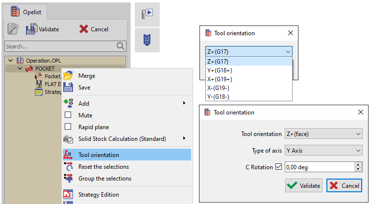
Tool Orientation In the opelist manager, we have added the ability to define the tool orientation for each operation. Milling and Turning dialogues present different options. |
|
|
|
|
Automatic References: add of a column Formula It enables to force the parameter Profile, altitude, etc according to a parameter defined in the opelist. It leads to the parameterizing of the input of opelists, that may be done with its own dialog. |
||
|
|
Automatic References: we can now select Features (All the Features and Colour Features' as automatic references for manual operations (contouring, slotting, etc.) |
||
|
|
Simulation
|
||
|
|
|

|
|
|
|
In the dialog of Coordinates, we now display the name of the origin for each operation we simulate. |
||
|
|
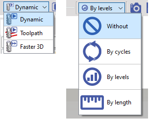
Icons have been added for the 2 combo lists:
|
|
|
|
|
Machine Tool Environment (MTE)
|
||
|
|
|
You can now create breakpoints to stop the simulation at that location for MTE Control and NC Control by either:
If you exit the MTE or NCcontrol simulation, the breakpoints are automatically saved. And when we restart the simulation, they are put back in place. If we save the part, the breakpoints are also kept. |
|
|
|
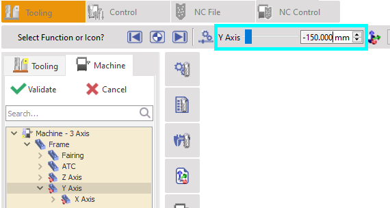
Tooling |
While editing an axis of machine, the value of the axis course is now displayed. |
|
|
|
Link of Axes |
New ability to link two axes together. You can apply this option while creating the machine. In creation of kinematic right-click on an axis and choose ‘Link a Component’. The purpose is to pilot two or several axes together. |
|
|
|
Tool numbering |
New possibility to modify the tool number hence changing the position of the tool after tool mounting. You can double click on tool support or right click on tool support then “Change position” to have a window to enter new tool support number. The target tool support have to be empty. |
|
|
|
The comparison function has been added in MTE Control. It is available directly while simulating the machining. When you play the simulation, the comparison is not active, but once you stop the simulation, the comparison is re-calculated. The comparison has also been improved, please watch a video here: Comparison |
||
|
|
2 Axis Milling & Shape
|
||
|
|
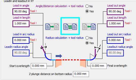
For Manual Operations, a new option has been added that allows to invert the parameters for the leadin and leadout. |
|
|
|
|
Outside angles: Under the options window, new toolpath option for the treatment of outside angles: generate loops. It enables to ensure good quality of corners. This is only possible for center toolpath (not part, compensation) |

|
|
|
|
Lateral passes in contouring Independent Passes is renamed into Compacted Passes. Compacted means that no retract is programmed between passes. The option is not available (grayed out) if the ‘Part’ toolpath is chosen: the passes will always be ‘independent’ (not compacted) and always have gain/loss of compensation for each pass. |
||
|
|
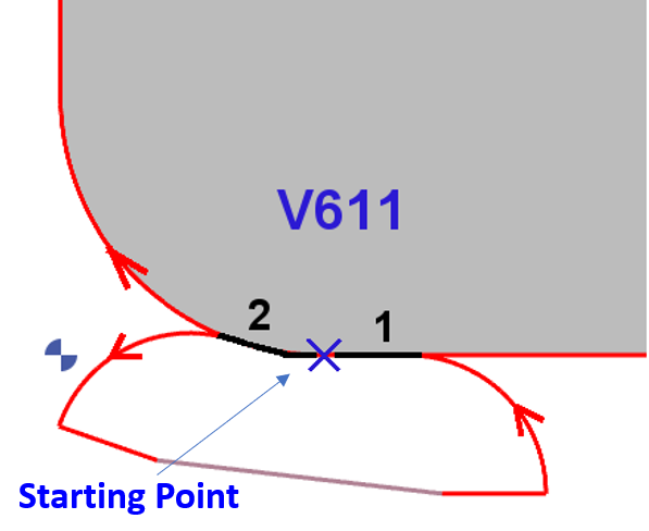
Improvement in the calculation of Overlengths for closed profile with 1st and last elements tangent. In V611, the overlengths take into consideration the shape of the profile. Start overlength (1) is tangent to Last Element and final overlength (2) is tangent to first element. |
|
|
|
|
2 new options in the Slotting:
|

|
|
|
|
Plunge Cycles |
We added chip-breaking options in the plunge contour and plunge pocket operations. |
|
|
|
New Leadin Rotation speed In strategy page,the Leadin Depth must have a value, unless Leadin Feedrate and Leadin rotation stay grayed out |
||
|
|
Gundrilling and Clevis |
Deep Drill and Clevis cycle have been separated into 2 cycles. Deep Drill has been renamed as Gundrilling. |
|
|
|
3 Axis Milling
|
||
|
|
User Interface |
The menu called ‘Multi-Axes Milling’ is now called Shape Milling. It used to include systematically the menus for 4 and 5 axis simultaneous, while now there may be only 3 axis milling operations, due to the new structure of packages. |
|
|
|
Tooling |
The Lens Mill Cutter is available for more cycles:
|

|
|
|
Tooling |
The Oval Mill Cutter and Barrel Mill Cutter are now available for Z Level operation. |
|
|
|
4-5 Axis Simultaneous
|
||
|
|
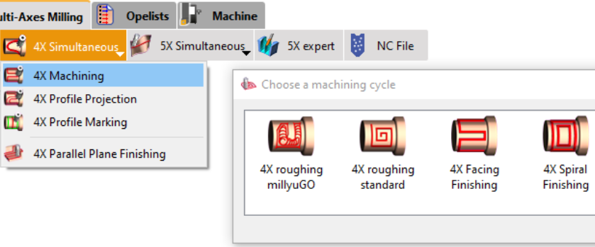
4Xs Cycles
|
Two new cycles have been added:
The submenu has been renamed to "4X Machining," encompassing both Roughing and Finishing operations.
You can watch a video presenting the 4Xs Roughing millyuGO operation and how to set it up. From V6.11.202, you are able to simulate these operations in realistic way by setting OFF the option ‘Simplified Machining’. |
|
|

|
|||
|
|
5 Axis Expert
|
|
|
|
The 5X Expert option has now a dedicated menu of same name. It is not anymore a submenu in '5X simultaneous' menu. |
|
|
|
Turning
|
||
|
|
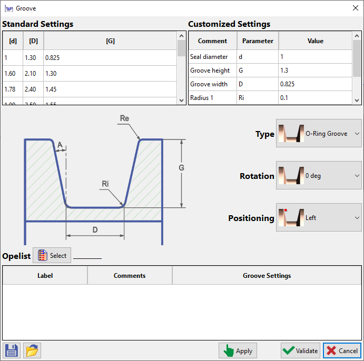
Groove Feature |
New command 'Groove' has been added under Shaft Creation to automatically design grooves on parts as per related standards and to assign opelists onto them. Also check Groove Feature in Turning for additional information. |
|
|
|
Feature |
New ‘Feature’ cycle added under ‘Part’ in the Turning tab. This runs the assigned opelist in ‘Groove’ feature to machine the part. |
|
|
|
New option that enables to create a table of feedrates associated to colours. When executing the cycle, the techno functions to change the feedrate are generated automatically. It enables to program a single toolpath on a whole shape with differing feedrates. |

|
|
|
|
Now we have a new Plunge type for the Zigzag groove cycle: This new Zigzag option enables the toolpath to simultaneously move into both axes at each step of the toolpath, providing a unique cutting approach.
|

|
|
|
|
New abilities to define pecking directions:
|
|
|
|
|
For manual Drilling operations there is the new ability to preselect the tool by filtering the tool diameter in the selection (same as the milling pocket). The list is reduced to capable tools with Tool Diameter <= Geometry Diameter The default diameter is calculated by the position of the picking point. |

|
|
|
|
Finish Groove operation: With method ‘In groove corner’, we have introduced a new option related to stepover to optimize the toolpath. |

|
|
|
|
When selecting geometry for the broaching cycle, you can now choose a solid edge instead of just a face (as in 6.10). The selected edge must be linear and collinear with the broaching axis for acceptance. Tool orientation is based on averaging normals of adjacent faces. |
||
|
|
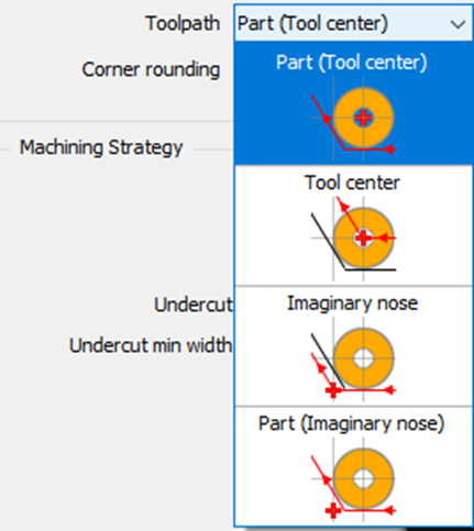
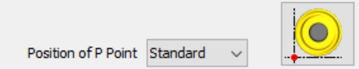
Management of P point in Part mode We have added a new type of toolpath calculation: Part (Imaginary Nose)
|
|
|
|
In this situation, we also advise forcing the P Point option directly in the tool page, so that you cannot have 2 different piloted points for the same tool! |
|
||
|
|
In the Chip-breaking management, we added the possibility to define a dwell at each retract. |
||
|
|
The safety parameters defined in Tools>Options>Turning now accept the value 0. This is dedicated to users who are used to design the leadin and leadout motions. Those values defined in the Options page are the default values that will be assigned to the parameters of all cycles: please note that it might be dangerous to switch them to 0! |
||
|
|
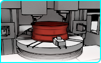
Vertical Turning
|
||
|
|
Product |
New product Vertical Turning:
|
|
|
|
Swiss Machining
|
||
|
|
New ability to slice the part in Z axis, to divide the machining in several areas along Z. Right-click on Material in the Machining tree to get access to the function.
When you validate there is no visible change in the geometry. These information are considered only during the application of an automatic opelist. |

|
|
|
|
Wire-Cut EDM
|
||
|
|
New automation in the process: Cutting Strategies are automatically applied to the profiles recognized by the command. For this, we added the concept of Typology into the definition of Strategies. Several types are available:
For the typologies of cylinders, we also have the ability to select a range of admissible diameters, to create strategies for holes from 0 to 10 mm, from 10 to 20 mm, etc. |

|
|
|
|
When we have only one solid in GO2cam, it is automatically selected while running the command. You can see it in the video. |
||
|
|
Cutting Conditions |
EDM code is added in the tools page. It is now taken into account if defined to link an ID to a material name for cutting conditions management. Before, the name of the material file was used only. |
|
|
|
Machine File |
The selection of Techno Tables is more simple. We deleted 2 entries of the combo box: Techno Table and Strategy table The creation of new tables is available only with mode ‘Sequences' |
|
|
|
Multi-Parts Machining (MPM)
|
||
|
|
Machine File |
Management of retracts between cycles We added a new option in the page Work-Holding Device>Evolution, to retract according to the device bounding box. |
|
|
|
User Workshop Document
|
|
|
|
Barcode is added in 3D window under Tool type. Beforehand, the barcode must be given in the tool page, in Options tab. The barcode is exported in the document as a bar. |
|
|
|
NC Control
|
||
|
|
Comparison |
Comparison function has been added. |
|
|
|
Breakpoints |
Breakpoints have been added. |
|
|
|
NC File |
Possibility to allow or not the modification of NC file inside NC Control for operators using "GO2cam Operator". So, in GO2cam we have a flag to activate or not in the operator's profiles & rights. |
|
|
|
GO2cam for SolidWorks
|
|
|
|
Import |
New possibilities with Solidworks :
|
|
|
External Links
|
|
|
|
Export |
New dialogs for Vericut / Eureka / Makino |