
|
|
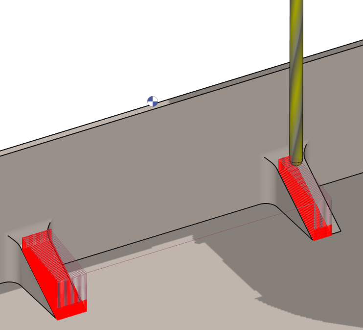
This cycle is used to machine reinforcement, a rib or a slope which shape is defined by its width and a side view. The principle is to define a specific plane, draw the geometry in it and then apply the machining cycle. |
Key Points
|
This operation is very specific since it can realize a 3 axis machining operation with only a 2D geometry. The steps to follow are as such:
|
|
|
Watch a video on the right demonstrating the workflow.
|

|
Strategy Parameters
|
Dialog Area |
Parameters |
|
|
Toolpath Strategy |
||
|
Corner type |
|
|
|
Profile Cutting |
Z step (Ap) |
Depth |
|
Thickness |
Incr. thickness |
|
|
Allowances |
|
|
Movement Parameters
|
Dialog Area |
Parameters |
|
|
Safety (in Z) |
||
|
Approach and return in Z |
||
|
Leadin and leadout in XY |
||
|
Leadin radius angle |
Leadout radius angle |
|
Technology Parameters
|
Dialog Area |
Parameters |
|
|
Cutting Conditions |
Quality |
Cutting Speed |
|
Feedrate/tooth |
Spindle direction |
|
|
Level |
Spindle speed |
|
|
Feedrate |
||
|
Sp. speed range |
||
|
|
||
|
Tool Numbering |
Tool number |
Specific Number |
|
Length compensation number |
|
|
|
Users Fields |
Comment |
Control Device |
|
Milling Set |
|
|
Options Parameters
|
Dialog Area |
Parameters |
|
|
Behaviour on the clamps and components |
||
|
Safety area |
||
|
Curves Computing |
Curve segmentation |
|