
|
|
List of new features and Improvements of GO2cam V6.12.201, released on 3 March 2025. Improvements added all along version’s life: Improvements of Revisions |
|
Icons used in the tables below |
|
New Features |
|
Improvements |
|
|
Web and Services
|
|
|
|
|
|
|
|
Installation, System & Hardware
|
||
|
|
The software installs to C:\Program Files\GO2cam_Intl\GO2camV612 by default, with the option to change this during setup. If an older V6.12 version exists, the installer suggests its directory for updating.
Special Case: Software Configuration (Options) is still saved in folder ini. One consequence to this new structure is to be able to work with GO2cam in multiple sessions in a safe way! |
||
|
|
The User directory can be cleaned with a new utility: DelUserConfig.exe. This specific executable file that can be ran out of GO2cam, in case of trouble. It is available in GO2cam directory and with Windows Search. |
||
|
|
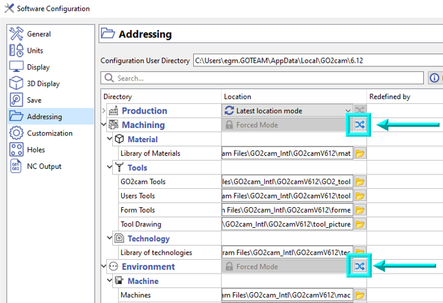
One other consequence of the new structure of directories is the possibility to reassign addressing locations collectively. A new button is available for Machining and Environment categories. |
|
|
|
|
OpenGL (3D Graphics) |
The graphics engine is more performant. Open GL 4.0 is more visually pleasing and performant and is also better managed by recent graphics card. For customers with older configurations, openGL 2.0 is also better managed. |
|
|
|
Application Programming Interface (API)
|
||
|
|
User Parameters for Opelists, PPs, and JavaScript |
|
|
|
|
Graphic User Interface
|
||
|
|
New Search command in the dialogue area You can type in the search bar and a dropdown menu will automatically suggest a list of functions that match the text. This search is based on the list of functions available in the product, and specifically in the language of the GO2cam product. Therefore, the search is in Italian if the software is launched in Italian. |

|
|
|
|
The GObot Virtual Assistant tool is now directly accessible in the GO2cam Software from the Status bar, with the ability to ask question about the use of the software itself, and specific coding with JavaScript API. |

|
|
|
|
In turning, by navigating to Tools > Options > Turning, users can change the default section view to any desired fraction. This section view is applied both in working window and in simulation window. Note that the section view will be applied to both the stock and workpiece. |
|
|
|
|
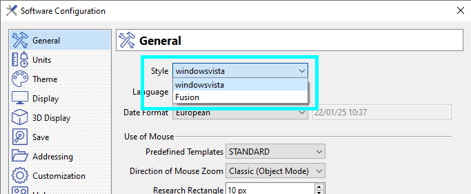
We can now choose from 2 windows Style in Software Configuration bringing in changes to icon sizes, font style and sizes, etc. |
|
|
|
|
Mouse manipulations: The default configuration (STANDARD) is now that of SolidWorks, to standardize with CAD/CAM software. The previous GO2cam configuration can be set by selecting the option 'GO2cam Legacy', accessible in the drop-down list of the Predefined Templates. |
|
|
|
|
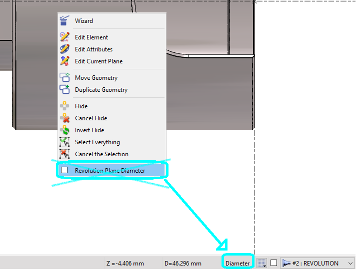
For design in Turning, the choice of Diameter or Radius coordinates has been moved from the popup menu to the status bar. It is a switch button. The current mode is the one visible in the status bar so that you have this information in the screen. |
|
|
|
|
A new export type has been added in File>Export providing the capability to export a graphic is the SVG (Scalable Vector Graphics) format for vectorial images. This format is used to renew the Print Preview making it more accurate and also introducing more options as shown in the screenshot. |

|
|
|
|
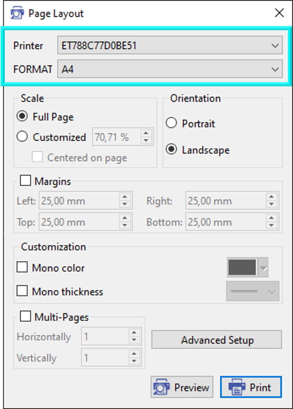
In Page Layout, the user can now directly chose the printer name and page Format. Almost all print setting can be done directly in GO2cam now. |
|
|
|
|
Filter Dialog |
The filter icon for workplanes is a little bit different and more explicite than in previous versions. |
|
|
|
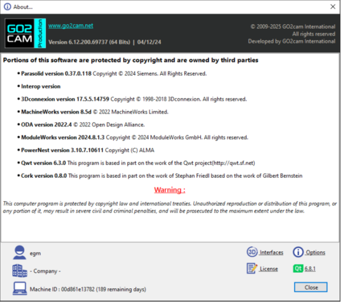
About |
We made minor adjustments to the About dialog. These changes included increasing its width to accommodate all necessary information on a single screen, thereby removing the need for users to scroll vertically. Additionally, we relocated the buttons within the dialog for improved accessibility and usability. |
|
|
|
Geometry Generalities
|
||
|
|
The module for the creation of milling shapes on a turning part has been renewed for some commands:
See the video on the right demonstrating the improvements. |
|
|
|
|
Rotation mode now includes an option to define the rotation angle between 2 points and the X-axis. 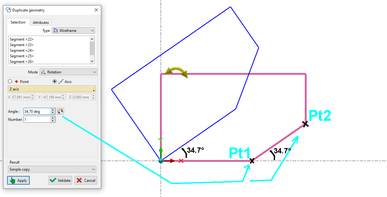
|
|
|
|
|
Geometric entities with names are displayed with their names in the title during editing. |
|
|
|
|
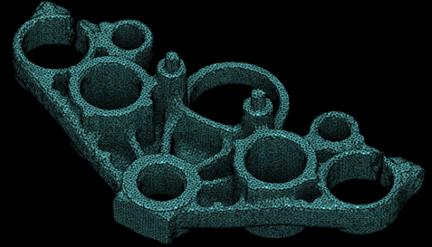
Mesh Design
|
||
|
|
A new Mesh menu has been added under the Design tab, offering functionality equivalent to Solid design, including creation, Boolean operations, hole recognition, and stop faces. Other new features regarding mesh elements:
All 3X, 4X, and 5X machining operations are supported on meshes, excluding surface-specific cycles like Isoparametric machining. |
|
|
|
|
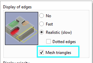
Mesh Triangles Display |
For mesh parts, users have the option to activate or deactivate the display of the mesh triangles. The option is available in the dialog box of the display options in the status bar. Check or uncheck the box for Mesh triangles to activate or deactivate its display. |
|
|
|
Mesh |
CAD interfaces can now read Mesh components included in the model. This was already possible for AutoCAD, Parasolid and STEP. It is now also possible with JT and Solidworks. |
|
|
|
CAD Interfaces
|
||
|
|
Creating 3D designs from 2D drafts has been improved. You now have the Axis System modes and a preview, making the process more intuitive. |
|
|
|
|
Some CAD interface formats have been updated in GO2cam V6.12:
|
||
|
|
Workplanes
|
||
|
|
We've refined workplane creation with a new intuitive approach. A single click on the Creation of planes function or drag-and-drop of the Interactive Axis System allows you to creates the most commonly used planes. A transparent preview square with an axis system visualizes the plane's orientation and position. For quick alignment, simply position the Interactive Axis System on the desired face of the blue cube displayed in the corner. See a video on the right demonstrating this feature. |
|
|
|
|
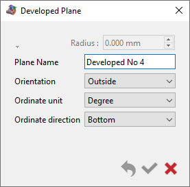
A new dialogue box has been introduced for creation of a developed planes. |
|
|
|
|
Symbols
|
||
|
|
The creation process for tools, symbols, machine, etc. has become more fluid with the interactive system of axes.
|
|
|
|
|
Tooling
|
||
|
|
New ability to export and import tool packs. Tool packs are *.GTZ file: compressed archive containing all the necessary files for any tool such as holder and form symbols. To share your tools with others, simply export them to a GTZ file with a right-click on the chosen tool. User tools or tools from GO2tools can be exported. Recipients can then easily import the files into their own libraries with a simple drag-and-drop or by using the dedicated import function. Watch the video below ( Tooling - Copy a Tool/Tool Catalogue) as from 00:59 for an example about the GTZ files. |
|
|
|
|
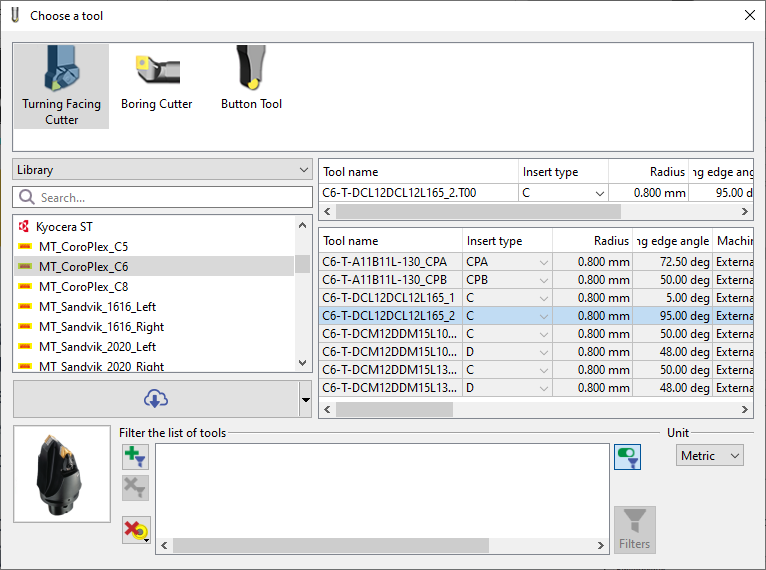
For tool catalogs or manufacturer tool files (GO2tool), you can now use the copy function to transfer a complete tool or all tools, including the cutter, holder, and symbol, into directories like tool, sym, and forme. This allows you to modify the tools locally. |

|
|
|
|
In the environment dedicated to symbols creation: a new function, Swiss machining tool is accessible under Creation menu. The whole process for the creation of Swiss machining form tools is now a wizard with the creation steps following one after the other making it more seamless. To launch the wizard, simply click on the GO button. 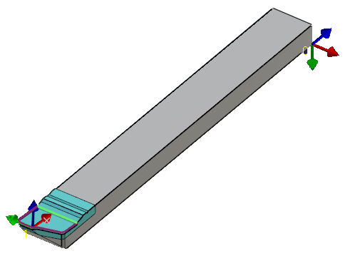
|
|
|
|
|
Tooling |
Clearance Option Added: now available for three more tools:
|

|
|
|
Tooling |
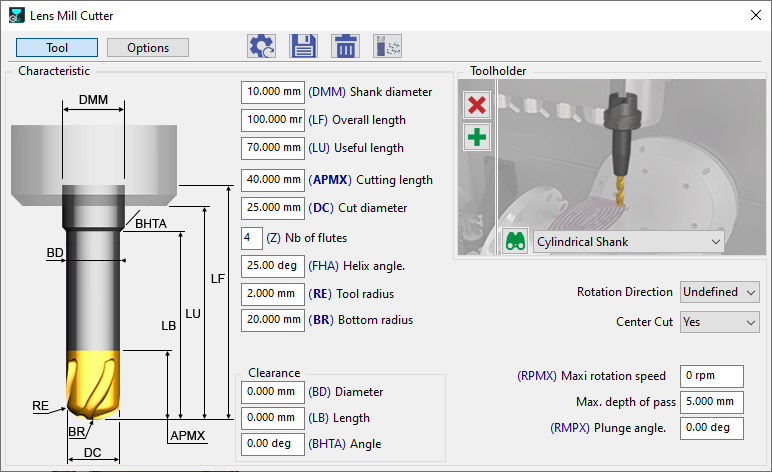
A new Flat lens mill cutter has been introduced, currently available for 5-Axis Expert machining operations. |
|
|
|
Flat end mill |
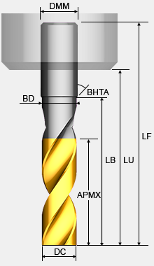
The icon of the Flat End Mill has been renewed and so is the graphic representation in the tool page. 
|
|
|
|
Machining Generalities
|
|
|
|
|
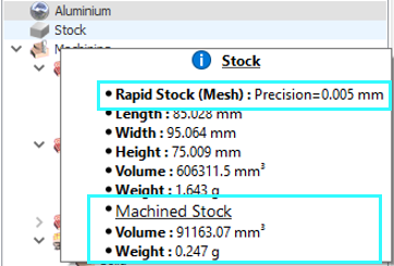
New Rapid Stock mode for the Stock Computation
|

|
|
|
|
Users can now define and save a catalog of predefined stocks to be used for different parts. These catalogues are separate from each product such as for Machining center, Lathe, Swiss machining, etc. All the parameters defined in the stock definition window, including those of the safety area are saved in the stock defined. |

|
|
|
|
When defining a stock shape from an existing solid or mesh, the user has the possibility to keep the solid entity instead of converting it completely to the stock by checking the box ‘Keep entity’. This allows quick modification of the stock shape by simply modifying the solid entity and doing an update. |

|
|
|
|
Stock |
In the Machining Tree, new information is now available in the tooltip, displaying the volume and weight of machined stock. |
|
|
|
Machine Pack |
Introducing the ability to export and import machine/post-processor packages as a single GSZ file. The package includes:
During import, files are automatically placed in the correct GO2cam directories (pp, ppstd, mac, kinemac, sym), simplifying installation and setup. |
|
|
|
Machine Origin |
In GO2cam, a unique origin can be assigned to an operation 'A' within the origin tables. If a new operation 'B' is created in the same geometric workplane as operation 'A', GO2cam automatically assigns and applies the same origin name. Previously, this was done automatically using 'Machining Planes,' which were removed in version v6.12. |
|
|
|
Machining Features
|
||
|
|
New Possibility to Close (Locally or Totally) an Open Pocket Feature The "open area on profile" function, is now also taken into account for features. This can help mitigate risks of tool collision. |

|
|
|
|
Opelists/Strategies
|
||
|
|
Introducing a New Opelist Feature that generate categorized Opelist lists with the Analyze function.
|

|
|
|
|
Similar to GO2dental, you can create a favorites list for your Opelists. To create a favorite, simply click on the star, which will turn blue and a new Favorites tab will then be created in the menu, displaying a list of your Opelists. |
||
|
|
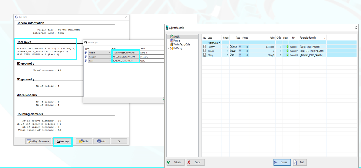
User Parameters for Opelists, PPs, and JavaScript |
Path: Help > File Info > User Keys
|
|
|
|
Simulation
|
||
|
|
Introducing a new feature that allows you to instantly run the simulation of a specific cycle without needing to calculate preceding operations. This functionality is accessible for every Milling and Turning operation within the Machining Tree, under the Simulation > Jump to Cycle option. |
|
|
|
|
We've introduced the ability to compare a specific cycle at a precise moment. Previously, comparisons included the entire machining list, and to focus on specific operations, you needed to set them to 'Waiting' status. This functionality is accessible for every Milling operation within the Machining Tree, under the Simulation > Compare this Cycle option. |
|
|
|
|
Machine Tool Environment (MTE)
|
||
|
|
Tool change points are now visible and display tips in MTE simulation. |

|
|
|
|
Breakpoints can now be enabled or disabled directly from the popup window. An active breakpoint (in red) will pause execution, while a disabled breakpoint (in green) will allow it to continue. This action can be performed from the Gantt chart or the NC program. |
||
|
|
Machine Magazine |
To adjust the number of tools in a magazine, simply modify the designated field on the machine numbering page. If this field is left empty (or set to zero), the system will automatically use the number of tools defined in the original MCG file. |
|
|
|
2 Axis Milling & Shape
|
||
|
|
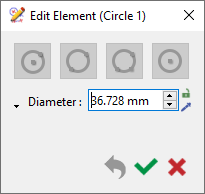
Previously, circles were machined in the direction of the active machining plane (e.g., vertically in the example). Now, the circle’s normal direction is respected automatically, eliminating the need to create additional planes. |
|
|
|
|
3 Axis Milling
|
||
|
|
|
|
|
|
|
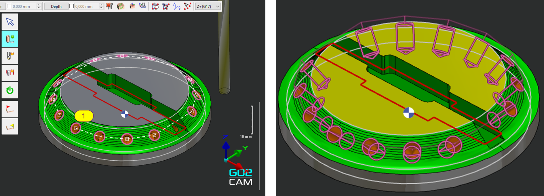
New Inversion of path parameter has been added for Auto Equidistant and Slope Equidistant cycles allowing to invert the machining path direction. |
||
|
|
5 Axis Expert
|
||
|
|
ModuleWorks |
Update to Version 2024.08 |
|
|
|
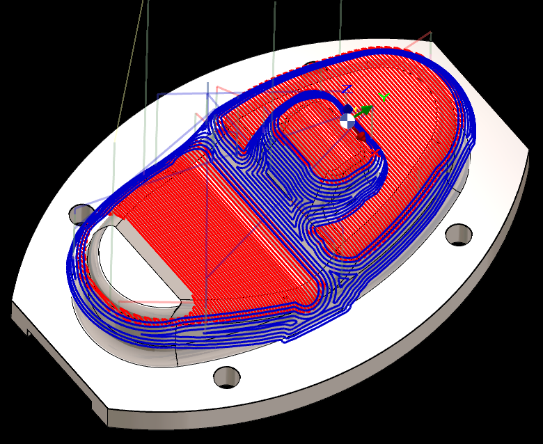
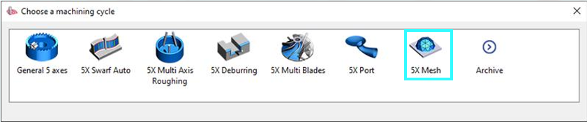
ModuleWorks |
New Cycle for Machining on MESH elements. |
|
|
|
Turning
|
||
|
|
The new End Facing operation introduces a range of advanced capabilities for machining part surfaces, including:
|

|
|
|
|
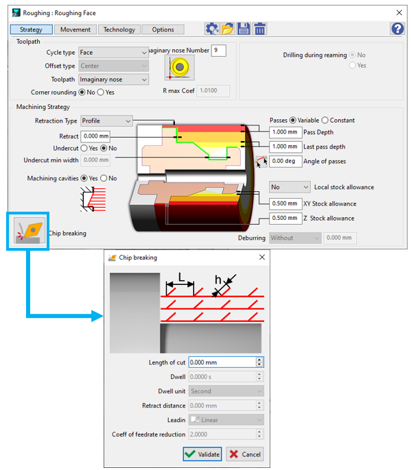
The Strategy page now includes a new dialog for Chip breaking, grouping all parameters for better comprehension
Cycles: Roughing, //Roughing, Balanced Roughing , TurnyuGO. |
|
|
|
|
A new "Continuous Optimized" option in alternate machining allows immediate machining of remaining material after grooving. |

|
|
|
|
A new option ensures that cavities are not machined. Cavities are different than ‘Pockets’: cavities are perpendicular to the toolpath direction, while pockets are parallel to toolpath direction. 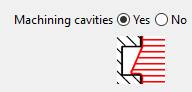
|
|
|
|
|
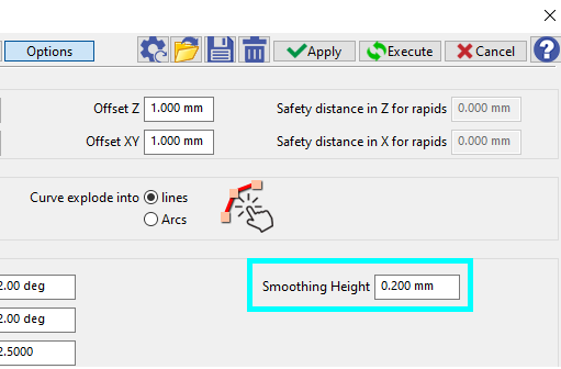
New parameter for Roughing cycle has been added in Options: Smoothing Height. This allows to set a maximum value enabling the removal of small parasitic ripples on a profile. Especially useful when profiles are curved. |
|
|
|
|
Wire-Cut EDM
|
||
|
|
In the Dialog of Filters, we added a new type of entity ‘Threading point’. It enables to distinguish threading points from geometric points. |
|
|
|
|
Multiple-Parts Machining
|
||
|
|
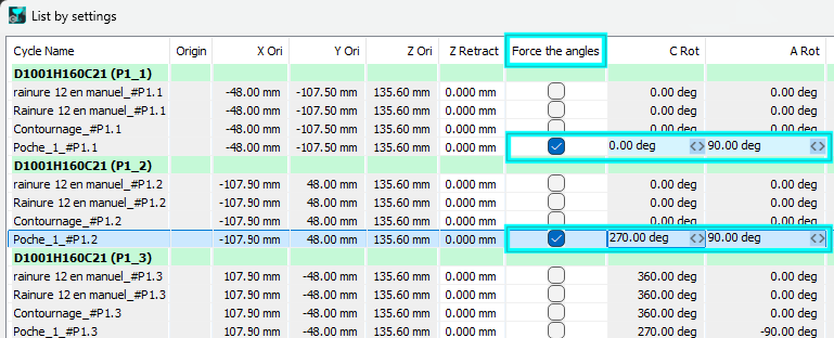
List by Settings |
We added a new option in the List by Settings that enables to choose among several possible combinations of angular positions. |
|
|
|
User Workshop Document
|
||
|
|
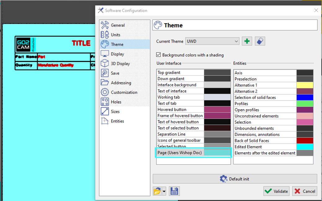
New possibility to modify the background color of your page. It can be set in the Theme page of Tools > Options menu. |
|
|