
Cycles: All Rough/Rework cycles
Limitation Area
|
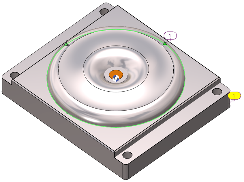
The Limitation Area parameter in GO2cam defines how the machining cycle interacts with the limitation area set to the workpiece. It can be applied in four modes, each controlling the toolpath differently. The example on the right, with the limitation profile, illustrates the various settings. |
|

|
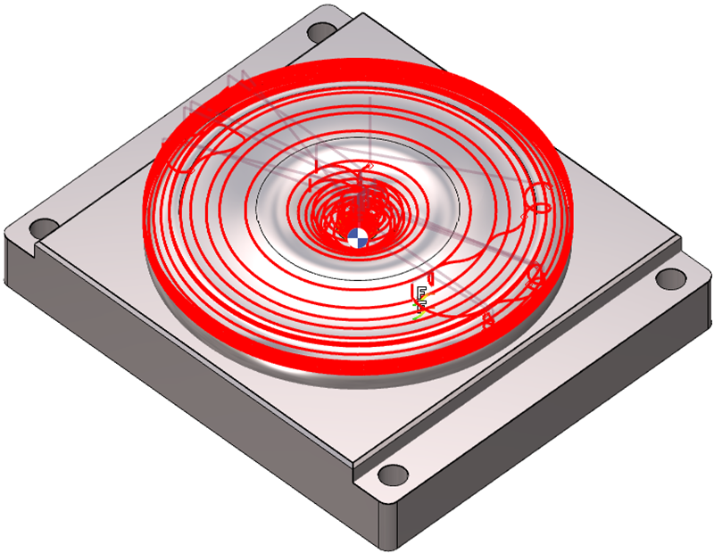
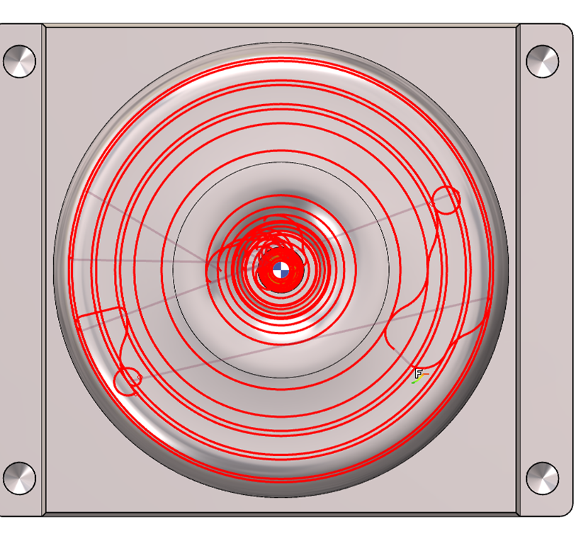
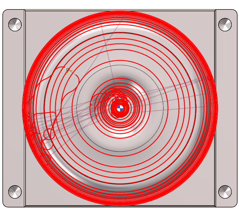
Enables the machining cycle to extend directly to the Limitation Area, stopping the toolpath exactly at the boundary. The illustrated toolpath reaches the boundary. |

|
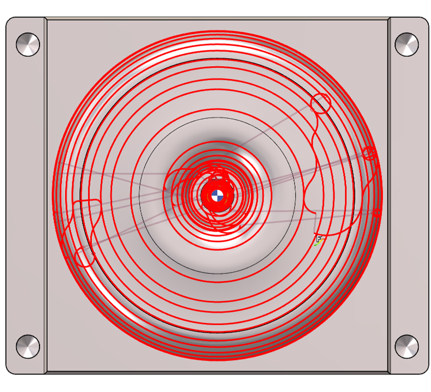
Keeps the machining cycle within the Limitation Area, stopping before the boundary to avoid edge contact. The illustrated toolpath stays within the boundary. |
||
|
|
|
|
||

|
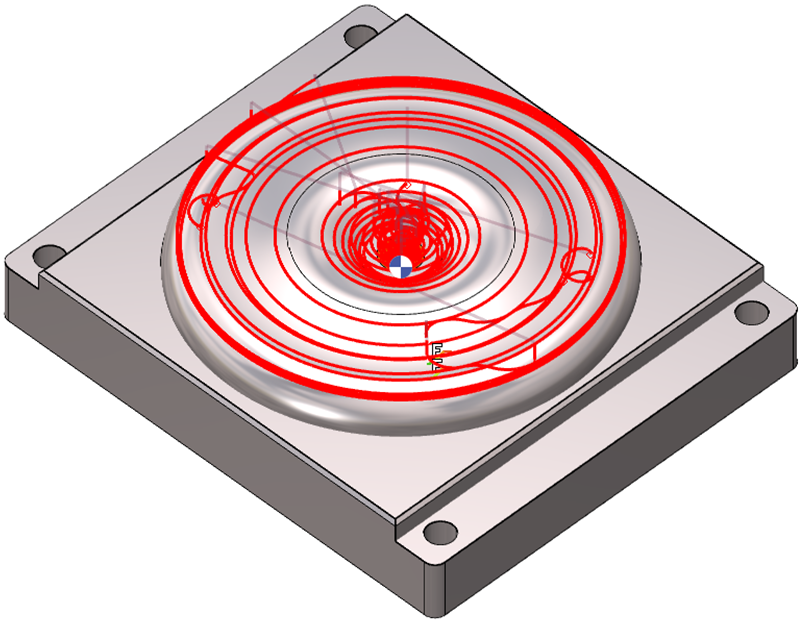
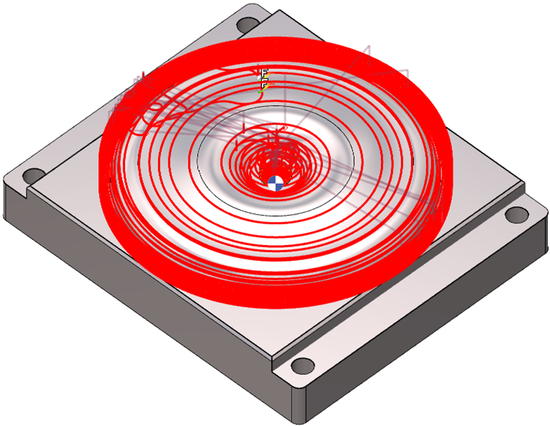
Enables the machining cycle to extend beyond the Limitation Area, positioning the toolpath outside the boundary while machining around it without cutting into the boundary. Note that the illustrated toolpath extends beyond the boundary. |

|
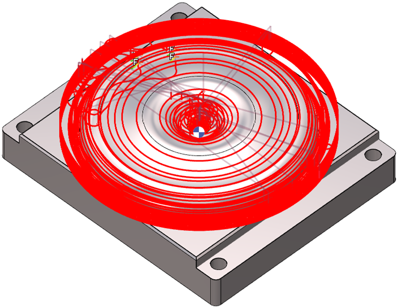
Enables the machining cycle to follow a distance relative to the Limitation Area. The user must input a value: zero places the toolpath on the Limitation Area, a positive value shifts it outside as in Parting Line, and a negative value shifts it inside as in Inside. The toolpath extends beyond the boundary to an arbitrary distance but can be adjusted accordingly. |
||
|
|
|
|
||
Mini machining area
This option prevents machining in very small areas, avoiding potential tool plunges and protecting tools without center cuts.
This parameter adds to the tool diameter to define the machining area.
|
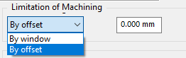
When setting limitation of minimum area to machine, there are two options:
The field value links directly to the tool diameter and adds to it to define the machining area. |
|
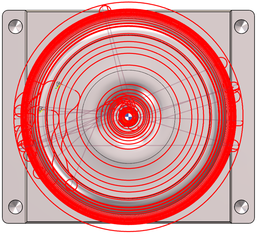
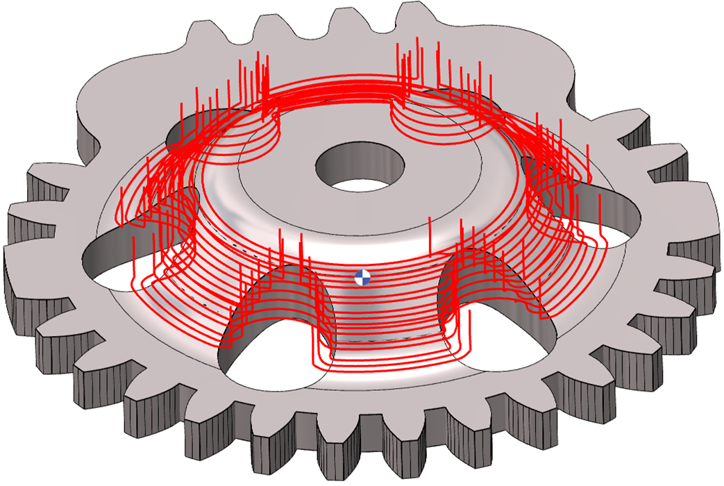
In this example, the cylindrical cavities have a diameter of 5.34 mm. The Limitation of Machining field is set to 5 mm. The tool diameter is 0.5 mm. The effective machining value is 5 + 0.5 mm = 5.5 mm, which exceeds the cavity diameter. Due to the offset limitation, the cavities are excluded during computation. |
|
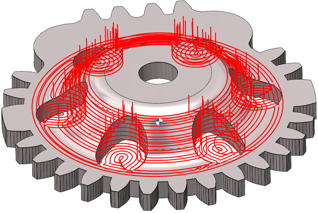
The same parameters apply. In this case, the By windows mode machines cavities or entities within the effective machining value. Cavity (5.34mm) < Effective machining value (5.5mm)
|
|
|
Entering a negative value modifies the area calculation to avoid. This value excludes areas based on size to prevent dangerous plunges. The profile offsets by this value; if no material requires removal, machining isn’t done. Essentially, the two modes' behaviors reverse. |
|
Tool offset for tool clearance
Details for this parameter can be found by clicking the link here.