Skip table of contents

Lead in/Lead out Interface

Cycle: Contouring, Contour Rework, Slotting, Taper cutting, Profile cutting, Chamfering, Finishing

Introduction

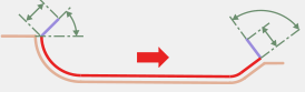
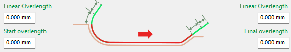
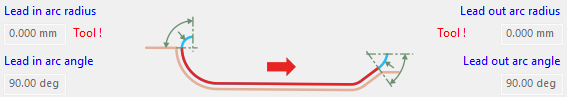
Lead in and Lead out movements define how the tool enters and exits a machining profile.
They are used to ensure a smooth engagement with the material and a safe disengagement from the part, helping to avoid marks on the finished surface and reduce tool stress.

New611.png

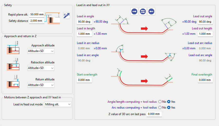
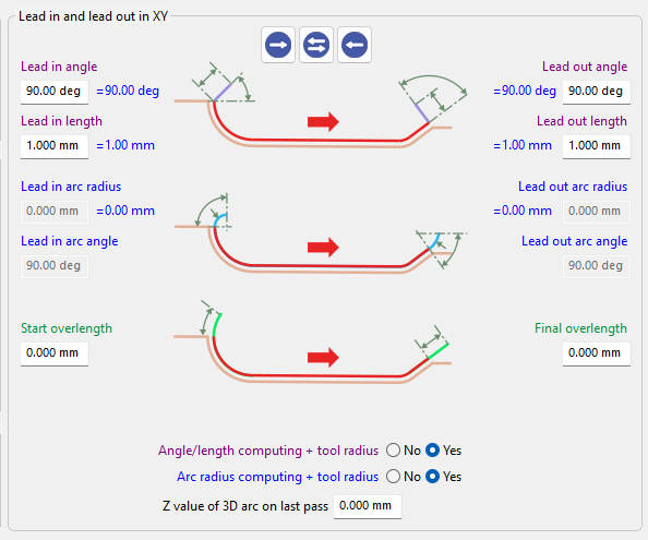
Lead in and Lead out interface has been redesigned to improve usability.
Although the layout has changed, all parameters and their functionality remain identical to previous versions.

Screenshot 2026-04-07 085258-20260407-045926.png

Characteristics

The Lead in/Lead out interface allows users to define and manage the tool entry and exit parameters in a clear and interactive way.

It provides direct control over the different Lead in and Lead out strategies, while offering visual feedback to help understand how each parameter affects the toolpath.

  1. There are three buttons to manipulate the parametric values:

  • Right arrow (→) – Copies all parameter values from the Lead in (left side) and applies them to the Lead out (right side).

  • Double arrow (↔) – Swaps the parameter values between the Lead in (left side) and Lead out (right side).

  • Left arrow (←) – Copies all parameter values from the Lead out (right side) and applies them to the (left side).

Screenshot 2026-03-10 141233.png
  1. A red arrow indicates the direction of machining, helping to clearly identify the toolpath orientation and the relationship between Lead in / Lead out.

Screenshot 2026-04-06 090434-20260406-051538.png
  1. The interface is also color-coded to improve clarity and parameter grouping:

  • Purple – Lead in/Lead out angle and length, including their associated computations

  • BlueArc parameters, including arc angles and arc radius with corresponding radius calculations

  • GreenOverlength parameters, including start and final overlengths calculations

purple arc thingu-20260407-051857.png
Screenshot 2026-04-07 085753-20260407-050048.png
Screenshot 2026-04-06 090536-20260406-050750.png
Screenshot 2026-04-07 085759-20260407-050122.png
Screenshot 2026-04-06 090543-20260406-050730.png
  1. If no tool is defined, the system displays a warning message, as the Lead in and Lead out calculations depend on the tool geometry.

Screenshot 2026-04-06 095919-20260406-055956.png

Related Parameters

For detailed information about each parameter, refer to the following sections.

JavaScript errors detected

Please note, these errors can depend on your browser setup.

If this problem persists, please contact our support.